B-1
OPERATION
STATIFLEX
®
6000-MS
OPERATION
Read and understand this entire section before oper ating your
Statiflex 6000-MS Filter Unit.
Safety Precautions
Do not attempt to use this equipment until you have thoroughly
read all operating and maintenance man uals supplied with your
equipment and any related welding machine it will be used with.
They include important safety precautions, operating and mainte -
nance instructions and parts lists.
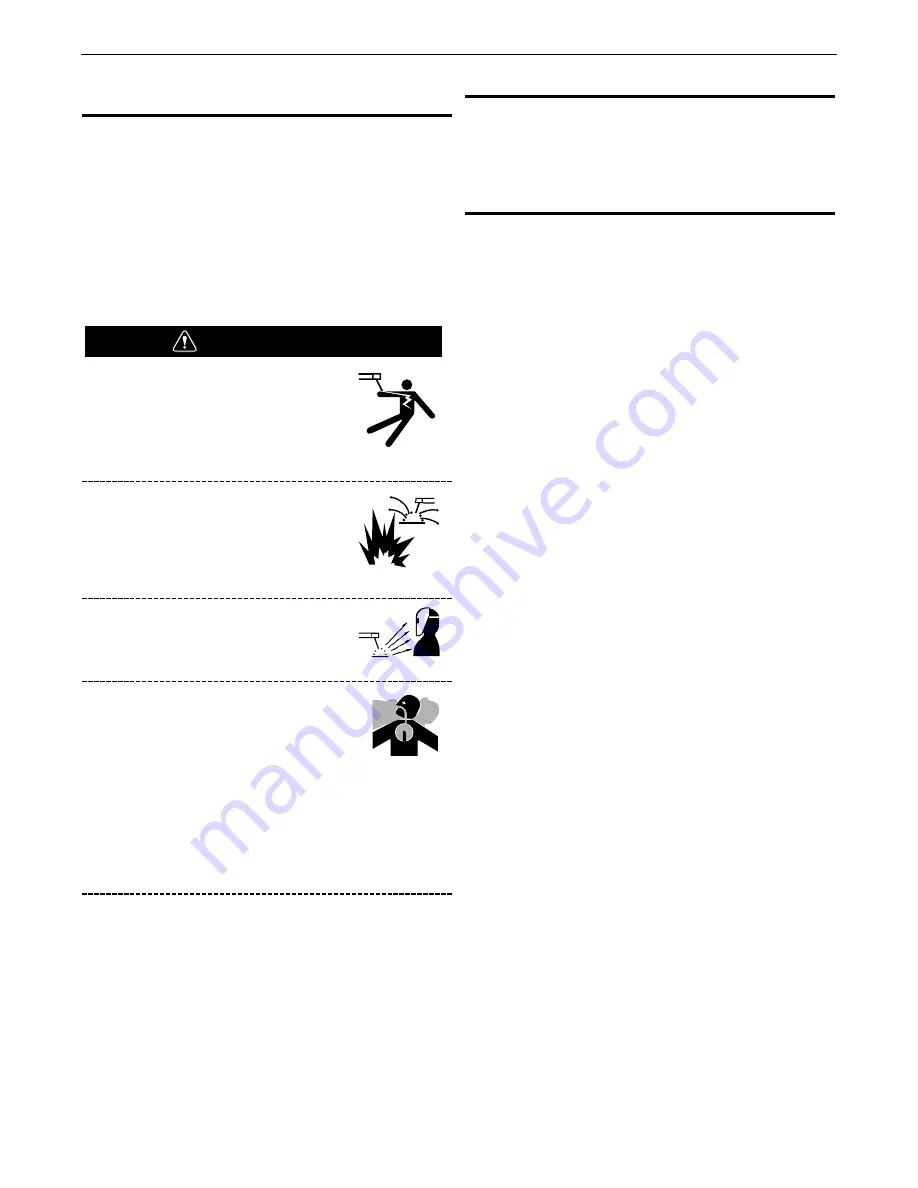
ELECTRIC SHOCK can kill.
•
Do not touch electrically live parts or
electrode with skin or wet clothing.
•
Insulate yourself from work and ground.
•
Always wear dry insulating gloves
WELDING SPARKS can cause fire
or explosion.
•
Keep flammable material away.
•
Do not weld upon containers which
have held combustibles.
ARC RAYS can burn.
•
Wear eye, ear and body protection.
FUMES and GASES can be dan-
gerous.
•
Although the removal of the particu late
matter from welding smoke may reduce
the ventilation requirement, concen-
trations of the clear exhausted fumes and gases may
still be haz ardous to health. Avoid breathing concen-
trations of these fumes and gases. Use adequate
ventilation when welding. See ANSI Z49.1, "Safety in
Welding and Cutting", pub lished by the American
Welding Society.
Only qualified personnel should operate this equipment.
ADDITIONAL SAFETY PRECAUTIONS
Always operate this equipment with the filter and arm installed
and all covers in place as these provide max imum protection from
moving parts and insure proper vacuum operation and cooling air
flow.
OPERATING INSTRUCTIONS
The operation of fans and extraction arms is covered under
manuals shipped with that equipment. The fol lowing instructions
refer primarily to the filter cleaning system of the Statiflex 6000-
MS
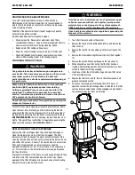
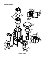
The inlet of the Statiflex 6000-MS is the upper con nection on the
corner of the unit. The outlet is in the middle, at the bottom. Dirty
air enters the inlet (usually through the preseparator to remove the
larger parti cles), passes around the baffle and through the filter
cartridges. The standard cartridges are cellulose (paper); polyester
replacements are available. The clean air passes through the
inside of the cartridges, downward and through the outlet. The
filter cartridges filter out 99.8% of the particles, but do not remove
gases. While typically not produced in large quantities in the arc
welding environment, the build-up of these gases should be
avoided. Plasma cutting commonly produces noticeable amounts
of gases such as oxides
of Nitrogen (NOx). Exhaust air from plasma cutting (after filtering)
should be exhausted outside where applicable.
A preseparator is strongly recommended for most applications and
is mandatory for cutting applications.
Lincoln Electric should review the system design of any system
used for cutting to verify best protection against risk of fire in the
filter cartridges.
As the filters collect fume on their surfaces, the pres sure drop will
increase and airflow will decrease. A fil ter cleaning system is
installed to keep the pressure drop at a reasonable and stable
level. This system operates automatically due to pressure drop
and/or preset times, or manually. Compressed air from the
reservoir tank blows through several holes in the cleaning tube,
knocking dust and fume from one sec tion of the filter cartridges.
The cleaning tube then rotates to the next section of the filters and
waits while the tank refills with compressed air.
Automatic cleaning due to pressure drop
The cleaning system will automatically signal a cleaning pulse due
to increased pressure drop. When the pres sure drop across the
filters reaches a set point, one cleaning pulse is signalled. The
system then waits for further signals. During normal operation, the
indicator light will blink quickly. During the cleaning cycle, the
indi cator light will be on all the time. If the cleaning pulse does not
reduce the pressure drop below the set point, the system will
continue to pulse. If the pressure drop is not reduced below the
set point after 240 pulses (approximately 4 hours), the indicator
light will blink slowly and the alarm buzzer will sound.
To deactivate the alarm buzzer and alarm status of the indicator
light, press the start/reset button on the control box. Work can
continue while the cause of the alarm is determined. The cleaning
system will continue to attempt to lower the pressure drop below
the set point for anoth er 240 pulses.
WARNING


