background image

Sa

le

s a

nd

 S

erv

ice

 th

ro

ug

h Su

bs

id

ia

rie

s an

d Dist

ribu

to

rs W

orld

w

id

e

Cl

ev

el

an

d, Oh

io

 44

11

7-

119

9  U

.S.

A.

TH

E LIN

CO

LN

 ELECT

RIC

 C

O

M

PANY

W

or

ld's Le

ad

er

 in

 W

elding

 an

Cuttin

Prod

ucts

FC051

700

058

0P

RI

NT

F.

11

ITIT

E

M


D

E

S

C

R

IP

T

IO

N


Q

T

Y

P

A

R

T

 N

U

M

B

E

R

E

IT

E

M


D

E

S

C

R

IP

T

IO

N


Q

T

Y

P

A

R

T

 N

U

M

B

E

R

M

IT

E

M


D

E

S

C

R

IP

T

IO

N


Q

T

Y

P

A

R

T

 N

U

M

B

E

R


IT

E

M


D

E

S

C

R

IP

T

IO

N


Q

T

Y

P

A

R

T

 N

U

M

B

E

R

D

IT

E

M


D

E

S

C

R

IP

T

IO

N


Q

T

Y

P

A

R

T

 N

U

M

B

E

R

E

IT

E

M


D

E

S

C

R

IP

T

IO

N


Q

T

Y

P

A

R

T

 N

U

M

B

E

R

S

IT

E

M


D

E

S

C

R

IP

T

IO

N


Q

T

Y

P

A

R

T

 N

U

M

B

E

R

C

IT

E

M


D

E

S

C

R

IP

T

IO

N


Q

T

Y

P

A

R

T

 N

U

M

B

E

R

R

IT

E

M


D

E

S

C

R

IP

T

IO

N


Q

T

Y

P

A

R

T

 N

U

M

B

E

R

I

IT

E

M


D

E

S

C

R

IP

T

IO

N


Q

T

Y

P

A

R

T

 N

U

M

B

E

R

P

IT

E

M


D

E

S

C

R

IP

T

IO

N


Q

T

Y

P

A

R

T

 N

U

M

B

E

R

T

IT

E

M


D

E

S

C

R

IP

T

IO

N


Q

T

Y

P

A

R

T

 N

U

M

B

E

R

I

IT

E

M


D

E

S

C

R

IP

T

IO

N


Q

T

Y

P

A

R

T

 N

U

M

B

E

R

O

IT

E

M


D

E

S

C

R

IP

T

IO

N


Q

T

Y

P

A

R

T

 N

U

M

B

E

R

N

IT

E

M


D

E

S

C

R

IP

T

IO

N


Q

T

Y

P

A

R

T

 N

U

M

B

E

R


IT

E

M


D

E

S

C

R

IP

T

IO

N


Q

T

Y

P

A

R

T

 N

U

M

B

E

R

Q

IT

E

M


D

E

S

C

R

IP

T

IO

N


Q

T

Y

P

A

R

T

 N

U

M

B

E

R

T

IT

E

M


D

E

S

C

R

IP

T

IO

N


Q

T

Y

P

A

R

T

 N

U

M

B

E

R

Y

IT

E

M


D

E

S

C

R

IP

T

IO

N


Q

T

Y

P

A

R

T

 N

U

M

B

E

R

IT

E

M


D

E

S

C

R

IP

T

IO

N


Q

T

Y

P

A

R

T

 N

U

M

B

E

R

IT

E

M


D

E

S

C

R

IP

T

IO

N


Q

T

Y

P

A

R

T

 N

U

M

B

E

R

IT

E

M


D

E

S

C

R

IP

T

IO

N


Q

T

Y

P

A

R

T

 N

U

M

B

E

R

IT

E

M


D

E

S

C

R

IP

T

IO

N


Q

T

Y

P

A

R

T

 N

U

M

B

E

R

IT

E

M


D

E

S

C

R

IP

T

IO

N


Q

T

Y

P

A

R

T

 N

U

M

B

E

R

IT

E

M


D

E

S

C

R

IP

T

IO

N


Q

T

Y

P

A

R

T

 N

U

M

B

E

R

IT

E

M


D

E

S

C

R

IP

T

IO

N


Q

T

Y

P

A

R

T

 N

U

M

B

E

R

IT

E

M


D

E

S

C

R

IP

T

IO

N


Q

T

Y

P

A

R

T

 N

U

M

B

E

R

IT

E

M


D

E

S

C

R

IP

T

IO

N


Q

T

Y

P

A

R

T

 N

U

M

B

E

R

IT

E

M


D

E

S

C

R

IP

T

IO

N


Q

T

Y

P

A

R

T

 N

U

M

B

E

R

IT

E

M


D

E

S

C

R

IP

T

IO

N


Q

T

Y

P

A

R

T

 N

U

M

B

E

R

1

TRAN

S

FORMER

1

2F

U

S

E 2.0A-250V

1

3

W

EEK TIMER 

S

WITCH

1

4P

U

L

S

E RELAY 

1

5

S

OLENOID

3

6

S

I

G

NAL LAMP

1

7

BUZZER

1

8

S

WITCH 1

9

D

IFFERENTIAL PRE

SS

URE 

S

WITCH

1

10

PRINT CONTROL 

S

C

S

 BOARD

1

11

PRINT 

S

C

S

 JUMPERED BOARD

1

12

TERMINAL BLOCK PU

S

H-IN

2

13

TERMINAL BLOCK PU

S

H-IN 

G

ND

1

14

TERMINAL BLOCK PU

S

H-IN END COVER

1

15

DIN RAIL 3 INCH LON

G

1

NOT

ES

:

N.

A. PU

LSE R

ELAY

 SET

TI

NG

 T

 ON

 - 1 SEC

     T

 OF

F -

 1 M

IN

 15 SEC

N.B

. AL

L W

IRES

 UNL

ES

S I

NDI

CA

TE

 SH

ALL BE 18 AW

G

N.

C.

 SET

 PR

ESSU

RE

 SW

IT

CH

 T

O

 10 m

bar

N.D.

 FIE

LD

 W

IRI

NG

N.E

. W

ARNI

NG

 NE

VE

R CONNE

CT

 2

30

V

 W

HE

N CO

NFI

G

URE

D FO

R 1

15

V W

HI

CH 

     M

AY

 D

AM

AG

E T

HE C

IR

CU

IT

N.

F.

 M

AIN

S C

ABLE SH

AL

L BE U

L R

AT

ED

 3C


 C

U 1

6AW

G/1

8AW

G OU

TE

R D

IA 

 BET

W

EE

N 0.157 IN

 T

O

 0.433 IN


 / 4 T

O

 11 m

m

N.G

. CA

BL

E FOR S

O

LE

NO

ID “FI

LT

ER"

 S

HA

LL


 BE O

F D

IA BET

W

EEN

 0

.1

57 IN

 T

O


     0.433 IN

 / 4 T

O

 11 m

m

N.

H.

 D

ISC

ON

NE

CT

IN

G M

EAN

S AN

D BR

AN

CH

 C

IR

CU

IT

 P

ROT

EC

TI

ON

 SH

ALL BE 

 PR

OVID

ED

 BY

 T

HE IN

ST

ALLER

PU

LSE R

ELAY

OPT

ION

 - 1

DE

FA

UL

T

115V/50-

60H

z M

AIN

S

CONNECT

IO

N

0V

212 W

H

L

N

YE

1  

 8

OR

1 12

VT

1  6

VT

2  7

WH

 1

BN

1  2

OR

2 13

GR

1 14

P

+

-

RD  1

0

BL  11

BK2  4

A1

A2

15

A1

A2

15

16

18

226 BN

209 W

H

208 BK

N

L

213 BN

225 BN

205 BN

206 W

H

BK

BK

GN

/Y

E

BK1

BN

GN

/Y

E

BK1

BN

GN

/Y

E

BK2

BN

GN

/Y

E

BK2

BN

GN

/Y

E

BK2

BK1

BN

FIL

TER 1

FIL

TER 3

FIL

TE

R 2

FIL

TE

R 4

BK1  3

GR

2 15

BN

2  5

YE

2  

 9

210 VT

211 VT

214 BK

215 BK

216 BN

217 Y

E

218 Y

E

219 R

D

220 BL

221 OR

222 OR

223 GR

224 GR

 103 BK

202 BK

16

18

NC

ND

ND

 103 BK

120V

24V

J1

1

2

3

4

5

10

6

120V

T1

F1

TB1

WT

1

PR

1

PC

B2

S1

L1

B1

PS1

PCB1

2

1

2

3

4

5

5

5

5

6

7

8

9

10

12

13

11

OPTION

 - 2

0V

23

0V

24

V

J1

1

2

3

4

5

10

6

IN

SU

LA

TE

& S

ECU

RE

10

3BK

10

3BK

20

2BK

230V/50-

60Hz

 M

AINS

 CONN

ECT

ION EX

AM

PL

E

T1

1

E-3

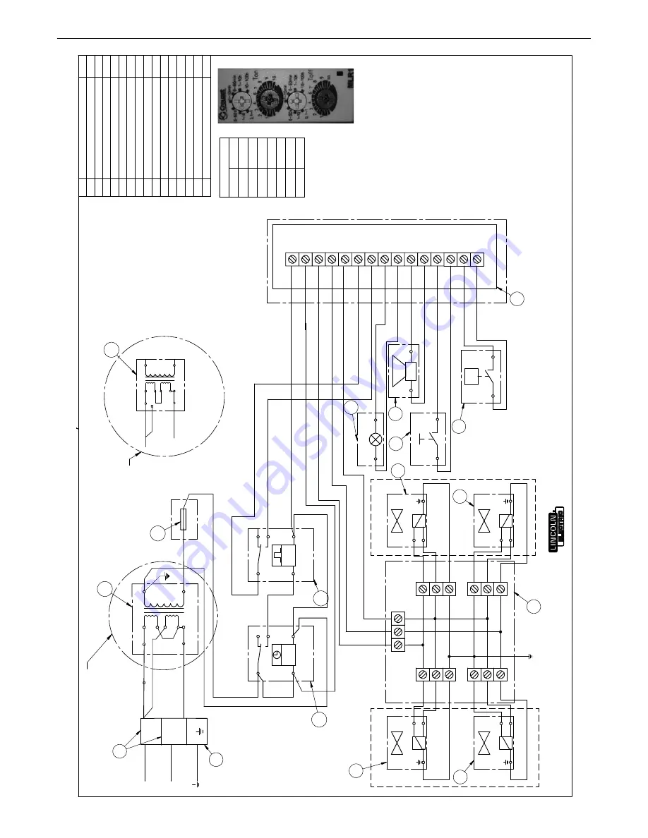
DIAGRAMS

STATIFLEX

®

6000-MS

Summary of Contents for Statiflex 6000-MS

Page 1: ...utor Locator www lincolnelectric com locator IM735 A Issue Date Feb 19 Lincoln Global Inc All Rights Reserved For use with machines having Product Numbers L10393 3 Filtration Unit Controls M18440 1 Preseperator Save for future reference Date Purchased Code ex 10859 Serial ex U1060512345 Operator s Manual ...

Page 2: ...N A LARGE ROOM OR OUTDOORS natural ventilation may be adequate if you keep your head out of the fumes See below USE NATURAL DRAFTS or fans to keep the fumes away from your face If you develop unusual symptoms see your supervisor Perhaps the welding atmosphere and ventilation system should be checked WEAR CORRECT EYE EAR BODY PROTECTION PROTECT your eyes and face with welding helmet properly fitted...

Page 3: ...ers and devices in position and in good repair Keep hands hair clothing and tools away from V belts gears fans and all other moving parts when starting operating or repairing equipment 1 e In some cases it may be necessary to remove safety guards to perform required maintenance Remove guards only when necessary and replace them when the maintenance requiring their removal is complete Always use th...

Page 4: ...m to ANSI Z87 I standards 4 b Use suitable clothing made from durable flame resistant material to protect your skin and that of your helpers from the arc rays 4 c Protect other nearby personnel with suitable non flammable screening and or warn them not to watch the arc nor expose themselves to the arc rays or to hot spatter or metal FUMES AND GASES CAN BE DANGEROUS 5 a Welding may produce fumes an...

Page 5: ...ent passing through lifting chains crane cables or other alternate circuits This can create fire hazards or overheat lifting chains or cables until they fail 6 h Also see item 1 c 6 I Read and follow NFPA 51B Standard for Fire Prevention During Welding Cutting and Other Hot Work available from NFPA 1 Batterymarch Park PO box 9101 Quincy MA 022690 9101 6 j Do not use a welding power source for pipe...

Page 6: ...used to capture welding fume at or near the arc and filter conta minants out of the air The ventilation or exhaust needed for your application depends upon many factors such as Workspace volume Workspace configuration Number of welders Welding process and current Consumables used mild steel hardfacing stainless etc Allowable levels TLV PEL etc Material welded including paint or plating Natural air...

Page 7: ...http www aws org Supplemental Information Not listed Nuisance value maximum is 10 milligrams per cubic meter PEL value for iron oxide is 10 milligrams per cubic meter TLV value for iron oxide is 5 milligrams per cubic meter As respirable dust Subject to the reporting requirements of Sections 311 312 and 313 of the Emergency Planning and Community Right to Know Act of 1986 and of 40CFR 370 and 372 ...

Page 8: ...ADDITIONAL SAFETY PRECAUTIONS B 1 OPERATING INSTRUCTIONS B 1 ACCESSORIES SECTION C REPLACEMENT FILTER OPTIONS C 1 MAINTENANCE SECTION D ROUTINE SERVICE MAINTENANCE D 2 REPLACING THE FILTER CARTRIDGES D 2 TROUBLESHOOTING GUIDE SECTION E PARTS LIST PARTS LINCOLNELECTRIC COM Content details may be changed or updated without notice For most current Instruction Manuals go to parts lincolnelectric com ...

Page 9: ...ATIONS STATIFLEX 6000 MS GENERAL NET WEIGHT 550 lb 250 kg MAXIMUM AIRFLOW 3 750 CFM 6 400 m3 h FILTER SURFACE AREA 1 400 tt2 total 130m2 COMPRESSED AIR 75 90 PSI 5 6 BAR PRESEPERATOR NET WEIGHT 110 LB 50KG TO 61 13 23 43 112 16 47 19 13 25 25 87 50 ...

Page 10: ...t of the Statiflex 6000 MS through the outside of the filter cartridges and out the outlet The Statiflex 6000 MS uses an automatic filter cleaning system to maintain the filter and reduce maintenance costs Fume collected on the outside of the filter is knocked off by a blast of compressed air from the cleaning system Fume then drops into the dust collection drum at the bottom of the unit When the ...

Page 11: ...onneCtion of filter Base to frame 1 Locate the thick set of legs and prepare for installation of filter base See Figure A 5 FIGURE A 5 2 Insert leg connectors half way into leg frames See Figure A 5 3 Insert bolts and washers into lower holes and hand tighten See Figure A 5 4 Using a lift or hoist position the assembled filter base onto the leg assembly 5 Insert bolts and washers into upper holes ...

Page 12: ...n air passes through the inside of the cartridges downward and through the outlet The filter cartridges filter out 99 8 of the particles but do not remove gases While typically not produced in large quantities in the arc welding environment the build up of these gases should be avoided Plasma cutting commonly produces noticeable amounts of gases such as oxides of Nitrogen NOx Exhaust air from plas...

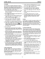
Page 13: ... board software The times for the clock timer operated cleaning however are adjustable using the timer relay to the right of the clock timer The cleaning pulse time upper dials is pre set to 1 second This should not be adjusted The pause time has a minimum one minute but can be increased using the lower dials For off line cleaning longer pause times allow the fine dust to settle to the drum Manual...

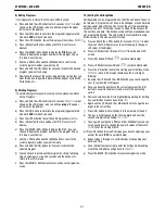
Page 14: ...s A1 and A2 This device is capable of viewing the time with no supply voltage present by pressing any of the control buttons for two seconds The 7DT 2CH display will illuminate and display pre set time When supply voltage is connected to terminals A1 and A2 the unit will continuously display the timing switch s status until supply voltage is removed 5 Illumination of Display The 7DT 2CH illuminate...

Page 15: ... or MAN buttons and than pressing the OK button automatic switching is activated v After correct symbol of the seasonal time has been chosen than press the OK button and the display will return to the SEt2 menu w Press the ESC MAN2 button to exit out of the program mode and back to the original run mode VI Programming 1 Mode Priorities 2 Normal Mode In the normal mode output is switched according ...

Page 16: ...displayed on the LCD screen g Use the PRG or MAN buttons to scroll through menu options so that the display looks like it does in step F EXCEPT the sign should now be blinking in the upper right of the display screen as well this is how the repeat cycle mode is activated h Press the OK button i The two hours digits on the left side of the display should be blinking adjust the numbers using the PRG...

Page 17: ...om 10 to 120 minutes Example use This mode is for irregular switching of appliances like a light which simulates presence of people in the house a Press and hold the PRG button for 3 seconds Set1is what shows on the LCD display also you will see prog in the upper left corner of the display b Press the PRG twice until the display shows Set3on the units LCD screen and the word MAN should also be ill...

Page 18: ...eturn to the deLmenu i Press the MAN 2 ESC button twice to exit back to original run mode 10 Setting the Holiday Mode Holiday mode can be programmed so that the unit doesn t have to be turned off programs don t have to be changed or even deleted during special times that you don t want the unit to be switching outputs on and off This mode is used to keep off the outputs for the set time and date T...

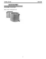
Page 19: ...C 1 ACCESSORIES STATIFLEX 6000 MS ACCESSORIES REPLACEmENT FILTER OPTIONS KP3367 1 Filter Set 2 Statiflex 6000 Circulator ...

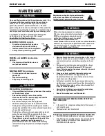
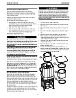
Page 20: ...ing the plastic sack disposal system supplied Maintenance should only be performed by authorized qualified and trained persons skilled using appropriate work practices When cleaning equipment or replacing filter use personal protection equipment PPE such as gloves respirators and protective clothing to protect against overexposure to particulate It is recommended that a vacuum cleaner or wet metho...

Page 21: ... THE FILTER CARTRIDGES Replace the filter cartridges when they have been damaged or when the indicator shows that the filter is clogged The filter indicator will flash slowly and the alarm buzzer will sound if the cleaning function does not reduce the pressure drop below the set point after 240 pulses 4 hours This could be due to a saturated filter Jack of compressed air low air pressure cleaning ...

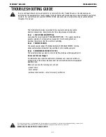
Page 22: ...nformation about specific adjustments maintenance or repair jobs which are not dealt with in this manual please contact Lincoln Electric Automation Department 888 935 3878 Make sure you have the following data on hand product name serial number purchase order number date for warranty verification If for any reason you do not understand the test procedures or are unable to perform the tests repairs...

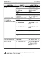
Page 23: ...ss fume or spatter from fan Fan seal damaged Check or replace sealing material of fan Dust or smoke coming out of outlet Filter damaged or not seated cor rectly Replace the filter or reseat it Alarm buzzer sounds Note To reset alarm press Clean reset button next to the indicater light Filter Saturated Replace Filter Compressed air not connected Connect compressed air 75 90 PSI clean cry Compressed...

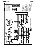
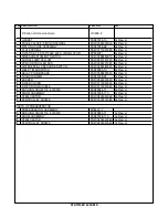
Page 24: ...IGNAL LAMP 1 7 BUZZER 1 8 SWITCH 1 9 DIFFERENTIAL PRESSURE SWITCH 1 10 PRINT CONTROL SCS BOARD 1 11 PRINT SCS JUMPERED BOARD 1 12 TERMINAL BLOCK PUSH IN 2 13 TERMINAL BLOCK PUSH IN GND 1 14 TERMINAL BLOCK PUSH IN END COVER 1 15 DIN RAIL 3 INCH LONG 1 NOTES N A PULSE RELAY SETTING T ON 1 SEC T OFF 1 MIN 15 SEC N B ALL WIRES UNLESS INDICATED SHALL BE 18 AWG N C SET PRESSURE SWITCH TO 10 mbar N D FIE...

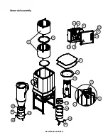
Page 25: ...STATIFLEX 6000 MS General Assembly 15 14 3 1 4 3 2 9 6 7 13 10 11 8 12 18 19 21 20 5 16 17 22 23 ...

Page 26: ...SURE SWITCH 9SFC0328280020 As Req d 10 WEEK TIMER SWITCH 9SS23385 10 As Req d 11 RELAY PULSE PAUSE 9SFC0328290050 As Req d 12 TRANSFORMER 9SS31228 92 As Req d 13 BUZZER 9SFC0360000020 As Req d 14 FILTER COVER 9SFC0719020040 As Req d 15 FILTER RING DOUBLE 9SFC0719020060 As Req d 16 BUSHING DRUM 100 6000MS 9SS23385 11 As Req d 17 DRUM ASSEMBLY 9SS31228 170 As Req d 18 STEM CASTOR 9SFC0805040060 As R...

Page 27: ......

Page 28: ......

Page 29: ......

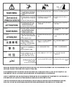
Page 30: ...parts or electrode with skin or wet clothing l Insulate yourself from work and ground l No toque las partes o los electrodos bajo carga con la piel o ropa moja da l Aislese del trabajo y de la tierra l Ne laissez ni la peau ni des vête ments mouillés entrer en contact avec des pièces sous tension l Isolez vous du travail et de la terre l Berühren Sie keine stromführenden Teile oder Elektroden mit ...

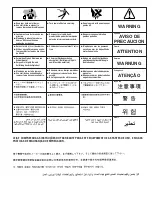
Page 31: ... und Entlüftung des Arbeitsplatzes l Mantenha seu rosto da fumaça l Use ventilação e exhaustão para remover fumo da zona respiratória l Turn power off before servicing l Desconectar el cable de ali mentación de poder de la máquina antes de iniciar cualquier servicio l Débranchez le courant avant l entre tien l Strom vor Wartungsarbeiten abschalten Netzstrom völlig öff nen Maschine anhalten l Não o...

Page 32: ... advice once it has been given nor does the provision of information or advice create expand or alter any warranty with respect to the sale of our products Lincoln Electric is a responsive manufacturer but the selection and use of specific products sold by Lincoln Electric is solely within the control of and remains the sole responsibility of the customer Many variables beyond the control of Linco...

Reviews: