B1
B4
B5
B6
B2
B3
87
W8
LEAD
W7
LEAD
POS
LEAD
POS
LEAD
NEG
LEAD
NEG
LEAD
88
PWM Input Present
Power at Recitifier Bridge
Chopper Operating
LED3
LED2
LED1
LXXXXX- X
FIGURE F.3 – LEADS & TERMINALS
CHOPPER MODULE RESISTANCE TEST
(CONTINUED)
PROCEDURE
1. Turn the engine off.
2. Perform the
Case Cover Removal procedure.
3. Perform the
Capacitor Discharge procedure.
4. Use a 7/16” wrench, label and disconnect the six
heavy black flex leads W8, positive, negative W7,
positive , negative from the Power Module PC
Board.
5. Using the 7/16’ wrench, remove the negative
jumper strap attaching the power capacitors to the
Power Module PC Board.
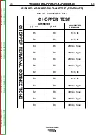
6. Check resistance with analog ohmmeter per the
“Chopper Test”
Table F.1.
Note:
Make sure the bolts do not fall back against the
heat sink.
7. Reconnect all leads.
Note:
The chopper module screw connections should
be tightened to 50-60 inch-pounds.
8. Perform the
Case Cover Replacement
Procedure.
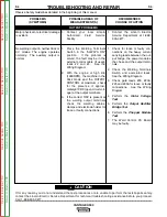
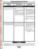
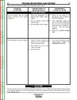
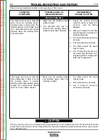
TROUBLESHOOTING AND REPAIR
F-18
F-18
VANTAGE® 500
NOTE: Early design P C
Boards did not have LED’s.
Board orientation may be dif-
ferent than what is shown.
Return
to
Section
T
OC
Return
to
Section
T
OC
Return
to
Section
T
OC
Return
to
Section
T
OC
Return
to
Master
T
OC
Return
to
Master
T
OC
Return
to
Master
T
OC
Return
to
Master
T
OC

