Shutdwn
Solenoid
Idler
Solenoid
LEADS
262
232M
265
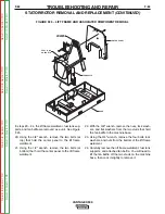
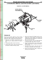
FIGURE F.18 – SHUTDOWN SOLENOID LINKAGE ARM ASSEMBLY
SHUTDOWN SOLENOID REMOVAL AND REPLACEMENT (CUMMINS)
PROCEDURE
1. Turn engine off.
2. Unlatch. lift and secure engine access door.
3. Locate and remove the spade connectors that
attach the shutdown solenoid terminals to the
wiring harness leads. Cut the cable tie.
4. Remove the bolts that mount shutdown solenoid
assembly to engine.
5. Remove the pivot pin retaining ring and pivot pin
from the solenoid linkage assembly.
6. Remove the solenoid assembly.
7. Replace any faulty or worn parts and reassemble
the solenoid assembly.
REASSEMBLY
1. Reassemble the pivot pin and retaining ring to the
linkage assembly.
2. Remount the shutdown solenoid assembly to the
engine.
3. Reattach the spade connectors from the wiring har-
ness to the shutdown solenoid assembly. Replace
the cable tie.
4. Close the engine access door.
TROUBLESHOOTING AND REPAIR
F-55
F-55
VANTAGE® 500
Return
to
Section
T
OC
Return
to
Section
T
OC
Return
to
Section
T
OC
Return
to
Section
T
OC
Return
to
Master
T
OC
Return
to
Master
T
OC
Return
to
Master
T
OC
Return
to
Master
T
OC

