background image


Low Profile –1600 Series Advantage Digital Service Manual -–Int’l


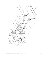
25


Summary of Contents for 1633-000-EA

Page 1: ...00 678 9511 lincolnfp com PARTS SERVICE MANUAL Impinger Low Profile Advantage Digital Series Gas International Models MODELS Please note that the model numbering system changed March 2007 The chart below shows the old model numbering system and its matching new model number Old Model Number New Model Number 1633 000 EA 1633 00z E Kxxxx 1634 000 EA 1634 00z E Kxxxx ...

Page 2: ...plies line voltage through the oven power relay through a three Amp fuse through the gas pressure switch gas pressure switch removed at S N L31479 through the main fan air pressure switch through the oven cavity hi limit thermostat to the ignition control The combustion motor is energized The normally open combustion air switch closes upon sensing air pressure After a pre purge period of between 3...

Page 3: ...Low Profile 1600 Series Advantage Digital Service Manual Int l 3 SCHEMATIC MODELS 1633 000 EA AND 1634 000 EA SERIAL NUMBER L28563 TO L31478 ...

Page 4: ...Low Profile 1600 Series Advantage Digital Service Manual Int l 4 SCHEMATIC MODELS 1633 00 EA AND 1634 000 EA SERIAL NUMBER L31479 AND ABOVE ...

Page 5: ...an relay No control box cooling Cooling fan s Supply voltage should now be at these motors If voltage is present check motor for open shorts or grounds WITH POWER OFF check for locked rotor Incoming power supply Check circuit breakers reset if needed Call power company if needed Cooling fan thermostat s Check the cooling fan thermostat thermostat closes at 120 F and opens at 100 F With the cooling...

Page 6: ...button If above fails replace ignition control Burner reset switch Switch is normally open Check to see that the switch closes when reset button is pushed Replace as needed Burner blower motor Check for supply voltage to burner blower motor WITH POWER OFF Turn blower wheel to check for locked rotor If supply voltage is present and motor does not run replace motor Burner blower motor Air pressure s...

Page 7: ...r replace air pressure switch as needed Oven cavity hi limit thermostat Terminals are normally closed opens at 350 C 660 F If open reset and test oven for proper operation If thermostat will not hold for maximum oven temperature and oven is not exceeding control setting check for proper location of capillary bulb in its spring holder If above checks are okay replace hi limit thermostat Ignition co...

Page 8: ...ion connect a digital multimeter capable of measuring D C microamps between the flame sensor wire and the flame sensor connection on the ignition control Sensor current is to be 0 9 microamps minimum If these readings are not achieved replace the igniter sensor assembly Also check for any type of damage to the flame sensor wire and connections NOTE The D C microamp test must be conducted with the ...

Page 9: ...l If the thermocouple is connected to the oven control and the control indicates LP FAIL or RP FAIL disconnect the thermocouple from the oven control and measure the resistance of the thermocouple The left thermocouple should read approx 21Ω The right thermocouple should read approx 11Ω If these readings are not achieved replace the thermocouple If these readings are correct proceed Oven control I...

Page 10: ...ansformer Check for line voltage supply to the primary of the control transformer If no voltage is present trace wiring back to the oven power relay If voltage is present check for 24VAC at the transformer secondary If there is primary voltage but no secondary voltage replace control transformer Conveyor motor Check for line voltage supply to the conveyor motor at wire 28 to neutral If no voltage ...

Page 11: ...he hall effect sensor Measure frequency across the yellow and white wires at the motor connector Frequency readings should be approx 25 100 Hz If these readings are not achieved replace the conveyor motor If the readings are achieved proceed Oven control If the hall effect sensor readings are correct but there is no speed indicated on the display replace the oven control ...

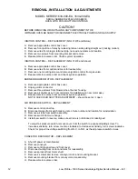
Page 12: ...ox cover B Unplug motor connector C Remove three screws from blower tube at burner housing D Remove air shutter assy From old motor for installation on new motor assy E Reassemble in reverse order and check system operation NOTE CHECK AIR SHUTTER ADJUSTMENT should be set at open AIR PRESSURE SWITCH REPLACEMENT A Remove control panel top B Disconnect wires from switch making note of wire number and...

Page 13: ...location F Disconnect pipe union just above gas valve and remove assembly G Reassemble in reverse order check all pipe fittings for leaks After assembled check for proper adjustment of gas pressure switch 10on dial for natural gas 27 for LP gas and 4 5 for town gas H Check and adjust manifold pressure Remove pressure tap located in gas piping above the gas valve prior to the burner orifice and ins...

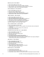
Page 14: ... appropriate control box cover B Disconnect wires from ignition control see ignition control Note wire number and location for reassembly C Pull off black operating knob and remove hex mounting nut D Reassemble in reverse order TEMPERATURE REGULATING VALVE REPLACEMENT A Remove appropriate control box cover B Remove bypass tube assembly C Remove 4 nuts from burner orifice bracket D Disconnect pipe ...

Page 15: ...rol box cover B Remove wires from relay note wire numbers and location for reinstallation C Remove 2 screws from relay base and replace relay D Reassemble in reverse order making sure wire connections are properly seated E Check system operation THERMOSTAT COOLING FAN REPLACEMENT A Remove appropriate control box cover B Remove 2 wires from thermostat note wire number and location C Remove 2 mounti...

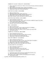
Page 16: ...m in oven chamber and remove from chamber NOTE R H thermocouple viewed from front is connected directly to the temperature control board remove 2 wires make note of wire colors and location When changing L H thermocouple viewed from front the back motor cover must also be removed to gain access to the thermocouple connector plug C Reassemble in reverse order making sure bulb is placed securely in ...

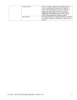
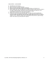
Page 17: ... 240V position Install the four push button extensions included with the oven control by pushing the extensions onto the four set buttons on control F Reassemble in reverse order and check system operation G Set the oven control for the proper operating mode The 1600 series ovens have dual burner systems The oven control must be set to the Dual oven mode Set control as follows With the oven power ...

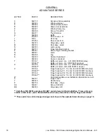
Page 18: ...eturn U L L R S N 35950 below 370663 Baffle air return U L S N 35951 above U 370166 Baffle air return U R L L S N 35950 below 370662 Baffle air return U R S N 35951 above V 370168 Finger housing T 1 T 3 B 2 B 4 S N 35950 below 370665 Finger housing T 1 T 3 B 2 B 4 S N 35951 above 370169 Finger housing T 2 T 4 B 1 B 3 S N 35950 below 370664 Finger housing T 2 T 4 B 1 B 3 S N 35951 above W Columnati...

Page 19: ...Low Profile 1600 Series Advantage Digital Service Manual Int l 19 ...

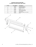
Page 20: ...08210000875 AND ABOVE LETTER PART NUMBER DESCRIPTION 369110 Access Door Assembly A 371140 Bracket Assembly Left B 371142 Dowel Access Door C 370722 Screw D 371143 8 32 x 3 8 Hx Serr Flng E 371141 Bracket Assembly Right F 370725 Dowel Thread G 371144 Access Door Frame top or bottom H 370723 Glass A B C D E F G H ...

Page 21: ...Low Profile 1600 Series Advantage Digital Service Manual Int l 21 This page intentionally left blank ...

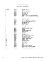
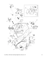
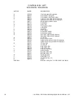
Page 22: ...r Switch L 369571 Connector M 370296 Wire Hanger N 369378 Cooling Fan O 369575 Air Pressure Switch P 369771 Reset Switch Ignition Control Q 369192 Capacitor R 369368 Hi Limit Thermostat Oven S 369574 Spark Generator T 357107 Fuse Holder U 369013 Fuse 3A 369014 Fuse 10A V 369579 Solid State Alarm W 369431 Thermostat Control Box Hi Limit X 369507 Thermostat Cooling Fan Y 370241 Transformer Control 2...

Page 23: ...Low Profile 1600 Series Advantage Digital Service Manual Int l 23 ...

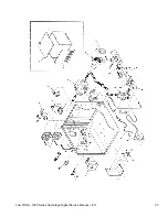
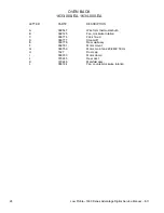
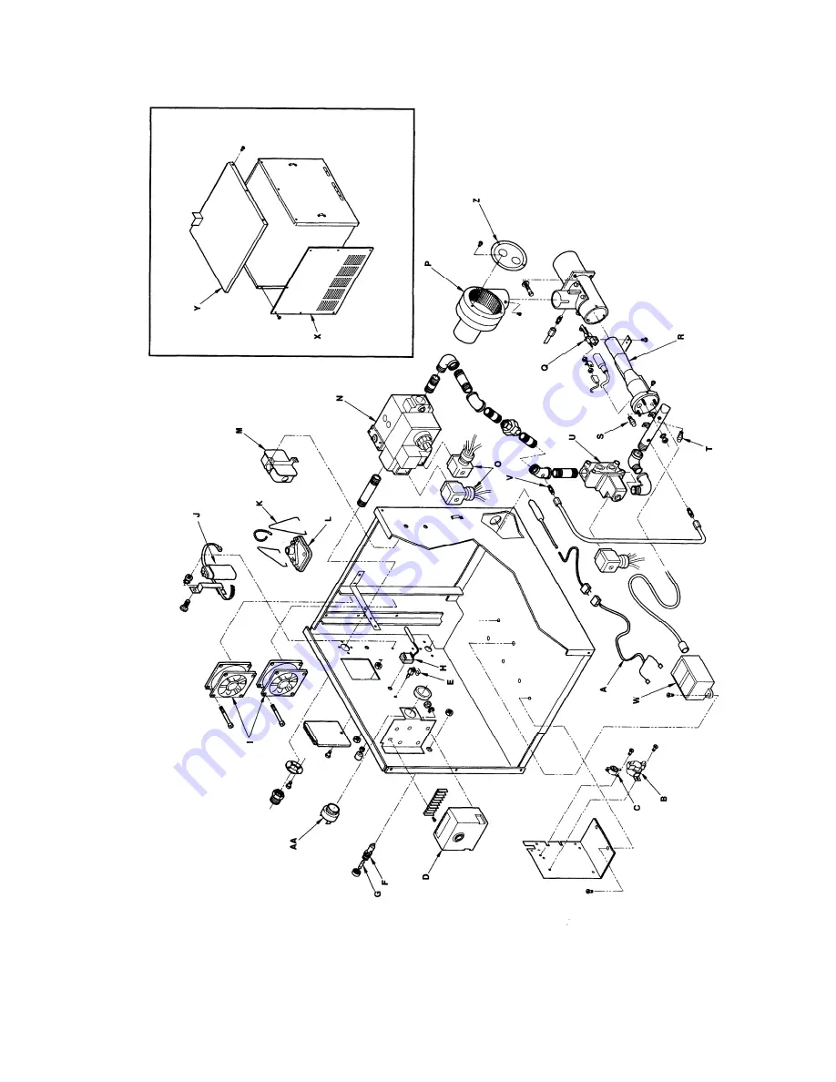
Page 24: ...an J 369192 Capacitor K 370296 Wire hanger L 369575 Air pressure switch M 369025 Air pressure switch N 369580 Gas valve S N L31478 below 370400 Gas valve S N L31479 above O 369571 Connector P 369589 Burner blower motor Q 369590 Igniter sensor assy S N 31478 below 370397 Igniter sensor assy S N 31479 above R 369937 Venturi Nat 369773 Venturi LP S 369757 Main orifice Nat 369758 main orifice LP T 369...

Page 25: ...Low Profile 1600 Series Advantage Digital Service Manual Int l 25 ...

Page 26: ...CRIPTION A 369547 Wire form thermostat bulb B 369725 Fan clockwise rotation C 369776 Fan shroud D 369777 Stand off E 369778 Rear wall assy F 369761 Motor mount G 369759 Motor main fan 220 240V 50 Hz H 1627 Duct cap I 369033 Motor clamp J 370245 Rear duct K 370246 Manifold assy L 368724 Fan counter clockwise rotation ...

Page 27: ...Low Profile 1600 Series Advantage Digital Service Manual Int l 27 ...

Page 28: ... belt 370092 Belt 1ft section 30 inch wide belt 369362 Belt 1ft section 32 inch wide belt B 369825 Retaining ring C 369813 Conveyor bearing block D 369314 Roll conveyor notched E 369812 Conveyor idler shaft F 369160 Conveyor pan stop G 369814 Connecting link 30 inch wide belt 369005 Connecting link 32 inch wide belt H 369811 Conveyor drive shaft J 369161 Roller chain sprocket K 369806 Crumb pan L ...

Page 29: ...Low Profile 1600 Series Advantage Digital Service Manual Int l 29 ...

Page 30: ...Low Profile 1600 Series Advantage Digital Service Manual Int l 30 This page intentionally left blank ...

Page 31: ...Low Profile 1600 Series Advantage Digital Service Manual Int l 31 This page intentionally left blank ...

Page 32: ...Low Profile 1600 Series Advantage Digital Service Manual Int l 32 ...

Reviews: