3
Form 402373
METER INSTRUCTIONS
CAUTION
Ensure the fluid supply to the meter is disconnected and
the line pressure is released before disassembly.
REGISTER AND GEAR TRAIN REMOVAL
1) Remove the protective shroud (22)
2) Peel off the meter faceplate (23)
3) Remove the 4 philips head screws (25)
4) Remove the register assembly (24)
5) Take careful note of the orientation of the gears on the
gear train, then carefully remove the gears (29,28,27,26)
Note: Assembly is a reversal of the disassembly procedure
.
6) Replace the gears (26,27,28,29)
Note: The register (24) is not repairable and will need to be
replaced if faulty or damaged.
7) Replace the register (24) and screws (25)
8) Assemble a new faceplate (23) onto the register face (24)
9) Re-assemble the protective shroud (22)
ROTOR REPLACEMENT
1) Remove the 8 philips head screws (33) from the
underside of the meter.
2
) Remove the coverplate (32) and o’ring (31 ).
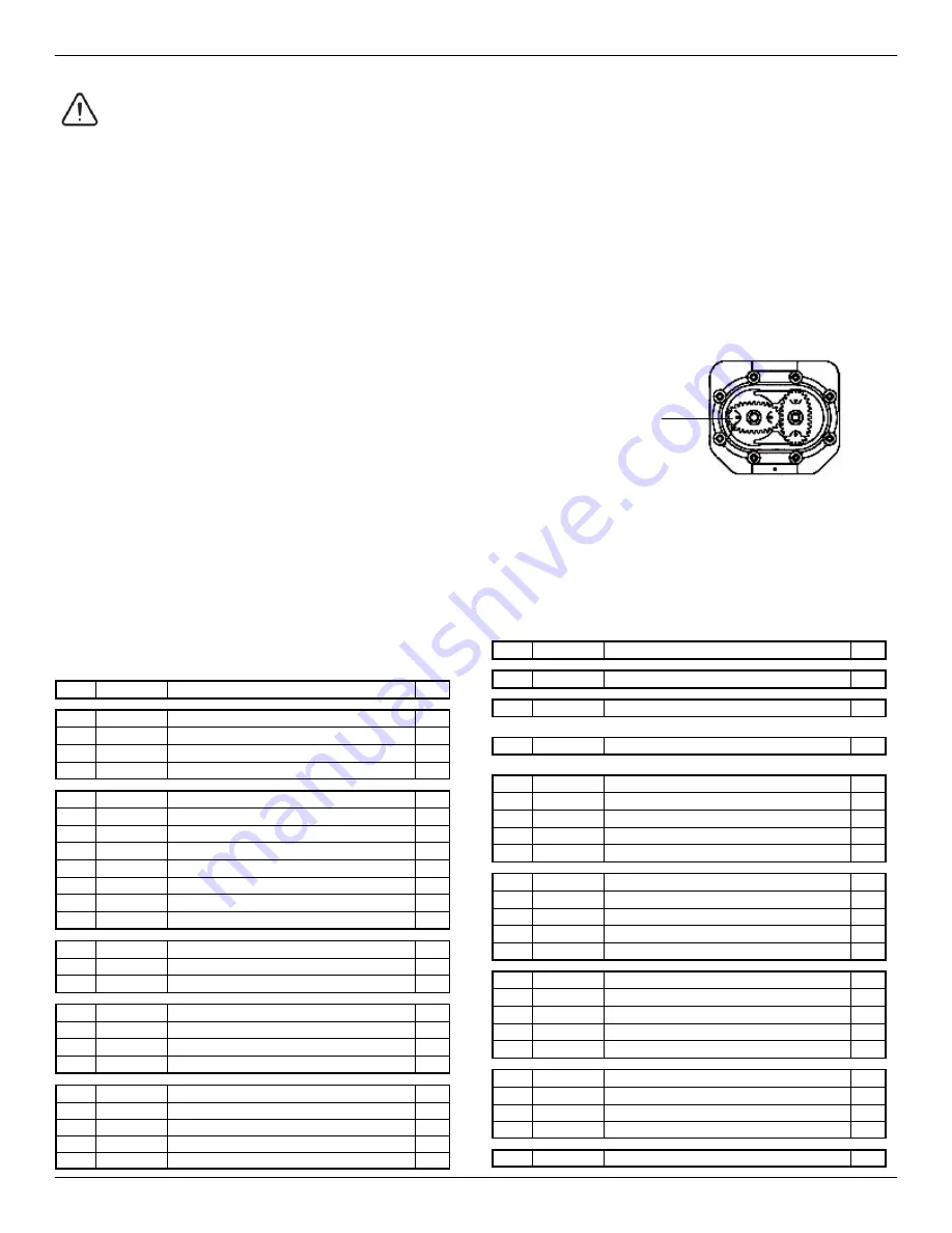
3) Remove both rotors (30) and inspect for any signs
of wear or damage. (Replace if worn or damaged)
NOTE:
Ensure the rotor with the magnets is assembled on the
correct side (Ref fig 2) The magnets in the rotor must face
towards the mechanical display .
1) Replace both rotors (30) positioned 90° to each other.
(see fig 2). Check rotation by turning the rotors. If the rotors
do not rotate freely remove one of the rotors and reinstall it
90° to the other. Recheck the operation of the rotors.
2) Lightly grease the o’ring (31) and place it on the meter body.
3) Clean the meter cover plate (32) and place it on the body.
Take care not to damage the o’ring (31).
The Rotor with Magnets
4) Install the 8 screws (33) and tighten in a diagonal pattern
to 0.73 ft.lb (1nm). Visual check the cap has been pulled
down evenly.
5) Test the meter by turning the rotors with a finger or by
applying low air pressure (No more than a good breath)
to the inlet port of the meter. This will confirm the meter
is operating correctly.
PARTS LIST
(
fig. 2)
ITEM PART NO. DESCRIPTION
QTY
3
276011
SWIVEL RETAINING RING 1/2" KIT
1
4
276012
SWIVEL ASSY 1/2" KIT
1
1
O-RING
1
2
STRAINER
1
3
SWIVEL RETAINER RING
1
276013
VALVE KIT
1
5
CIRCLIP
1
6
BACK SWIVEL BUSHING
1
7
QUAD RING
1
8
SPRING RETAINER CLIP
1
9
VALVE SPRING
1
10
VALVE BODY ASSY
1
11
VALVE STEM
1
276014
CAM KIT
1
13
CAM BODY
1
14
CAM O-RING
2
276015
HANDLE KIT
1
17
LEVER LATCHING
1
18
HANDLE WASHER
1
19
HANDLE SCREW
1
276016
HANDLE GUARD KIT
1
20
HANDLE GUARD ASSY
1
21
HANDLE SCREW (NOT SHOWN)
5
15
HANDLE END PLATE
1
16
SCREW
2
ITEM PART NO. DESCRIPTION
QTY
23
276017
FACE PLATE LITERS KIT
1
23
276018
FACE PLATE QUARTS KIT
1
23
276027
FACE PLATE GALLONS KIT
1
24
276019
REGISTER ASSEMBLY KIT
1
276020
GEAR KIT LITER
1
26
GEAR
1
27
GEAR
1
28
GEAR
1
29
BEVEL GEAR
1
276021
GEAR KIT QUARTS
1
26
GEAR
1
27
GEAR
1
28
GEAR
1
29
BEVEL GEAR
1
276028
GEAR KIT GALLONS
1
26
GEAR
1
27
GEAR
1
28
GEAR
1
29
BEVEL GEAR
1
276022
ROTOR KIT
(908M)
1
30
ROTOR SET
2
31
O-RING
1
33
Screw
8
22
276030
PROTECTOR SHROUD KIT BLACK
1


