B-1
OPERATION
IDEALARC® DC-400
B-1
SAFETY PRECAUTIONS
When using a DC-400 power source with wire feeders
which do not have an electrical trigger interlock (or
with wire feeders with the electrical trigger interlock in
the OFF position), there will be a small spark if the
electrode contacts the work or ground within several
seconds after releasing the trigger.
When used with some wire feeders with the electrical
trigger interlock in the ON position, the arc can restart
if the electrode touches the work or ground during
these several seconds.
• Be sure to select OUTPUT TERMINALS “REMOTE
ON/OFF” for operation with wire feeders that have
leads numbered 2 and 4.
ELECTRIC SHOCK
can kill.
• Have an electrician install and ser-
vice this equipment.
• Turn the input power off at the fuse
box before working on equipment.
• Do not touch electrically hot parts.
• This next section applies to DC-400ʼs without
the Capacitor Discharge Option:
WARNING
WARNING
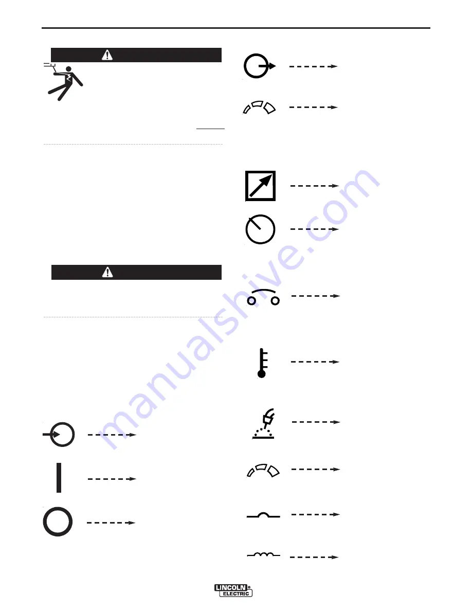
MEANINGS OF GRAPHIC SYMBOLS
The DC-400 nameplate has been redesigned to use
international symbols in describing the function of the
various components. Below are the symbols used.
POWER ON-OFF SWITCH
Input (Power)
On
Off
OUTPUT CONTROL DIAL
Output (Control)
Increase/Decrease of
Output (Voltage or
Current)
OUTPUT CONTROL “LOCAL-REMOTE” SWITCH
Remote Output Voltage
or Current Control
Local Output Voltage or
Current Control
CIRCUIT BREAKER
THERMAL PROTECTION LIGHT
ARC CONTROL SWITCH
Circuit Breaker
High Temperature
Gas Metal Arc
Welding
Increase/Decrease
of Inductance
Low Inductance
High Inductance
Summary of Contents for IDEALARC DC-400
Page 33: ...F 1 DIAGRAMS F 1 IDEALARC DC 400 ...
Page 38: ...NOTES IDEALARC DC 400 ...
Page 39: ...NOTES IDEALARC DC 400 ...


