Subject
to
change
without
notice
Owner Manual
Operating Instructions
2.1A-30004-A02
Page 12 of 36
LINCOLN GmbH & Co. KG Postfach 1263 D-69183 Walldorf Tel +49 (6227) 33-0 Fax +49 (6227) 33-259
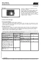
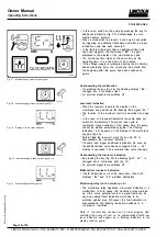
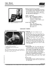
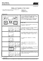
Fig. 16 - Fault indication in the case of a blockage
00002629a
Pressure Relief Valve
Important!
Each pump element must be secured with a
pressure relief valve.
The pressure relief valve
- limits the pressure build-up in the system
- opens when the respective overpressure is reached.
- must be selected according to the requirements of the
lubrication system (see different opening pressures: 200,
270, 350 bar).
If lubricant is leaking at the pressure relief valve, this
indicates a malfunction in the centralized lubrication
system or the lubrication point.
Note: There may arise a longer time delay between a mal-
function (blockage) and the consequential fault indication
(lubricant leakage; monitory: flashing display of Er on the
membrane key pad).
The duration of the delay depends on the type of line, the line
lengths, the type of lubricant, the ambient temperature and
other influences.
Despite the existing failure monitory, carry out a visual
control as well as a function control in regular intervals.
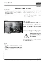
Pressure relief valve with grease return (optional)
If the system is blocked, grease will leak from the pres-
sure relief valve. This grease quantity is returned to the
reservoir.
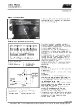
Fig. 14 - Pressure relief valve
10022618a
00002626b
Fig. 15 - Pressure relief valve with grease return
Pressure relief valve without grease return
In the case of a blockage in the system, the grease
pushes out the red pin at the pressure relief valve thus
indicating that there is a fault.


