STEP 5
-
-
-
-
8Amp
P2
RES
IGN
P1
12V
24V
M
+
+
+
+ -
-
+
1
2
1)
2)
-
Amp
8
P2
RES
IGN
P1
M
-
-
-
+
+
+
12 V
24 V
1
2
3
4
5
1)
2)
Fig. 26
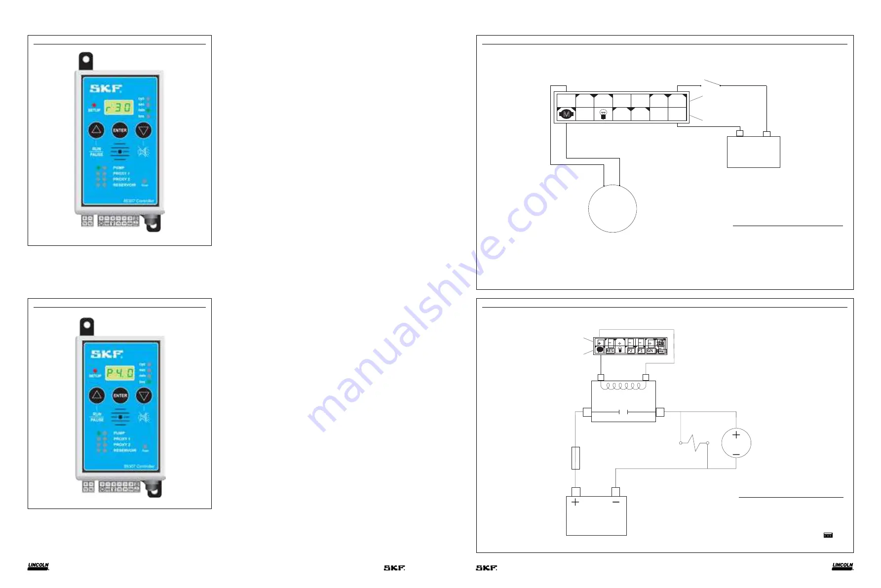
Running system (pump run)
Run (
r
) time displays when controller is switched on. Time appears
from actual time set and counts down to zero. Green LED indicates
minutes (
Fig. 26
). Green LED next to
PUMP
flashes to indicate pump
is turning or pumping.
Fig. 27
Running system (pump pause)
Controller enters pause time when required run time is reached.
Pause (
P
) time counts down from original setup time to zero and
then resumes run time (
Fig. 27
). Green LED is steady next to
PUMP
indicating pump is on but not turning while in pause mode.
Item
Description
1
Motor
2
Ignition
1)
Top row represents front of controller.
2)
Bottom row represents back of controller.
NOTE: If motor amp draw exceeds the maximum specification (
), solenoid relay switch (69897S) must be used. Refer to (
).
Item
Description
1
Fuse, 7.5 A
2
Solenoid relay switch
3
Motor
4
Vent valve solenoid (NO)
5
Power supply, 12 or 24 V
Diagram 1
Wiring diagram of progressive-line system without sensors
Diagram 2
Wiring of pump with solenoid relay switch
1)
Top row represents front of controller.
2)
Bottom row represents back of controller.
14
15


