STEP 9
STEP 9
A
B
STEP 9
STEP 11
A
B
Fig. 28
Setup mode
Progressive-line system with reservoir monitoring, run and pause time only
1
Refer to
steps 1-6
through
.
2
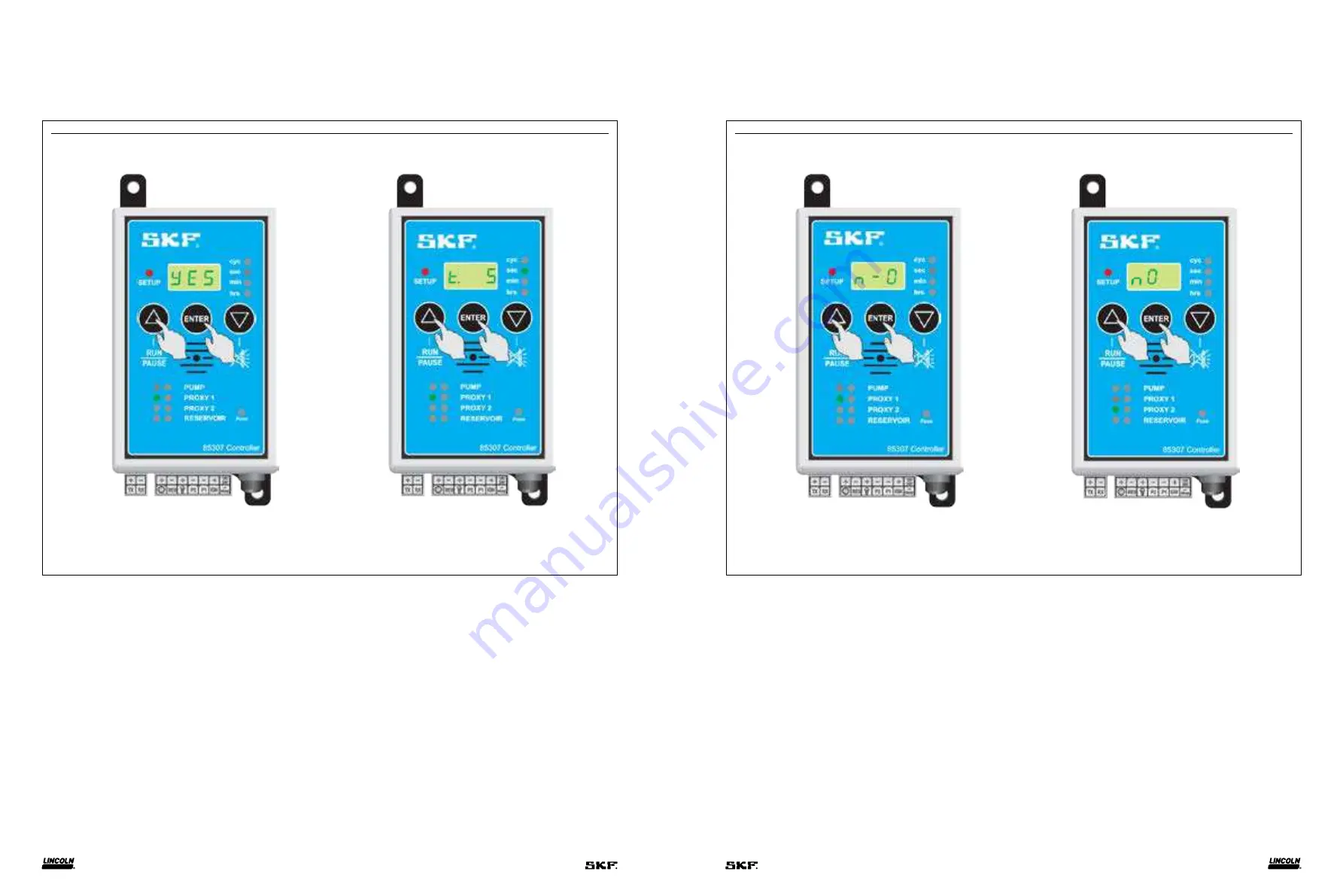
Select
Δ
or
∇
until
YES
appears in display to verify use of sensor
(
Fig. 28 A
). Green LED flashes next to
PROXY 1
indicating sensor
part of setup procedure.
3
Press
ENTER
to select
YES
and
PROXY 1
enters setup procedure.
4 t
(time out) appears in display indicating alarm will activate if
sensor does not send signal to controller within set time. This
function is used when flow proximity sensor is installed on feeder.
Within feeder, piston activates sensor and sends signal to
controller. Controller resets time out and starts counting down
to start monitoring process. This function continues to work while
in
RUN
mode. Set time out greater than cycle time of specific
feeder. This depends on type of pump being used.
Press
Δ
to increase time out to desired setting.
5
Press
ENTER
to confirm. In example, time out of 5 seconds is
confirmed (
Fig. 28 B
).
Fig. 29
6 n-O
(normally open) appears in display. Indicates if sensor is
normally open or normally closed.
7
Press
Δ
to choose between
n-O
or
n-C
.
8
Press
ENTER
to confirm choice (
Fig. 29 A
).
9 nO
appears in display. Green LED on
PROXY 2
illuminates.
If 2nd proxy is necessary, proceed by pushing
Δ
.
10
Press
ENTER
to confirm and proceed setup for
PROXY 1
.
11
For one sensor, press
Δ
until
nO
appears in display.
12
Press
ENTER
to confirm (
Fig. 29 B
).
16
17


