System Setup Information
When setting up the virtual equipment, the user must
set the welding parameters (e.g. wire feed speed for
VR GMAW) within the ranges set in the tolerance edi-
tor. The system ships with Lincoln default tolerances.
Lincoln default tolerances can be reviewed in the tol-
erance editor, or refer to the Default Weld Process
Settings Chart (if using the default settings) located at
the end of this OPERATION SECTION. The WPS’s
are also available on www.VRTEX360.com.
B-6
OPERATION
B-6
VRTEX
TM
360
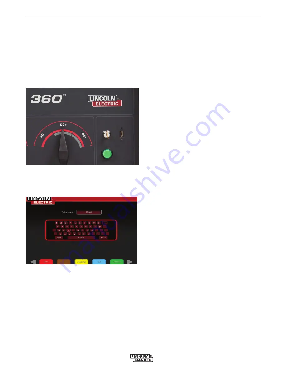
GREEN CIRCULAR BUTTON LOCATION
However, users can set and use their own tolerances
for teaching beginner welders. The tolerances also
determine how the user is scored on such parameters
as work angle, travel angle, travel speed, position,
and contact tip to work distance or arc length. The
software will step the user through the following setup
screens:
• Login
• Joint configuration selection
• Process selection
• Stand set up
• Environment
• Gas set up
• Weld machine settings
• Instructor’s view
• Welder’s view
• LASER (Live Action Student Evaluation Report)
The key provided with the system allows the user to
access the Instructor Mode with additional information
and set-up pages.
• Weldometer
TM
• Tolerance Editor
• Options
• Update
LOGIN SCREEN
4. Your system will start up.
5. Wait a few minutes until your system displays the
login screen on your monitor.
Powering Up Your System:
1. After you have set up the hardware and have
become familiar with the user controls, you will be
ready to use your system.
2. Plug the power cord into a standard outlet.
3. Press and hold the green circular button on the
front panel until it lights up and you hear fans run-
ning inside the machine. (approx. 3 seconds)
Summary of Contents for Vrtex 360
Page 2: ......
Page 50: ...NOTES VRTEXTM 360 ...


