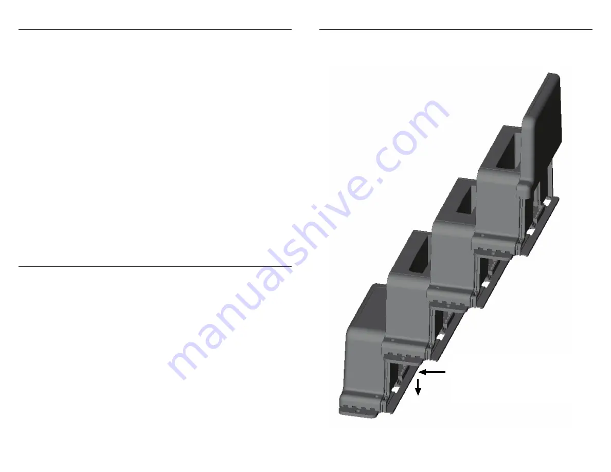
ASSEMBLY
To assemble the Charging Bays together, push up against previous module and slide
down to connect (see diagram below).
INDICATORS
Master controller:
– Constant green = Normal operation.
– Two quick amber flashes followed by two quick green flashes = Unknown AC power
adapter. Charging of batteries prevented. Use Dell AC power adapter or try removing
power cord to Master Controller, waiting 10 seconds and re-plugging it back in.
– Blinking red = Ambient temperature of system is colder than 32°F (0°C) or hotter
than 122°F (50°C). Charging of batteries is stopped. Resumes when back in normal
temperature range.
Charging Bay:
– No indicator = No battery in bay.
– Constant amber = Battery in bay but waiting for Master Controller to give it permission to
charge.
– Quick green blink once every 4 seconds = Battery charged and ready for use.
– Fast blinking green = Battery charging and greater than 80% charged.
– Slow blinking green = Battery charging and less than 80% charged.
– Quick blinking amber = Battery failure, stopped charging if started.
OPERATION
Once the system is powered up and ready for use, the batteries can be inserted into the
Charging Bays. Insert the batteries into the bays in the order you would like them to be
charged. The master controller will charge the batteries in the order inserted. The number
of bays charging simultaneously will be dependent on the power adapter being used. As
these batteries become fully charged and no longer need the charging power, the Master
Controller will select the next battery in the sequence to charge. If the charged battery is
removed and another discharged battery is inserted into a bay that unit will move to the
end of the sequence for charging. The Master Controller should have a green indicator on
during normal operation.
The Charging Bays will have:
– No indication if no battery installed.
– An amber indication if its battery is waiting for enough power to be freed up to start
charging it.
– A slow blinking green indicator if the battery is charging and is at less than 80% charge.
– A fast blinking indicator if charging and battery is greater than 80% charged.
– A quick green blink once every 4 seconds if the battery is fully charged and ready for use.
– See “Indicators” section for other error indications.
NOTE: If the system is powered up with batteries already inserted into the Charging
Bays the Master Controller will charge them starting with the bay closest to the Master
Controller and the farthest bay being last. Any batteries added to any empty bays after
this point will be moved to the end of the sequence. If power is lost all data the Master
Controller has regarding battery charging sequence is lost.


