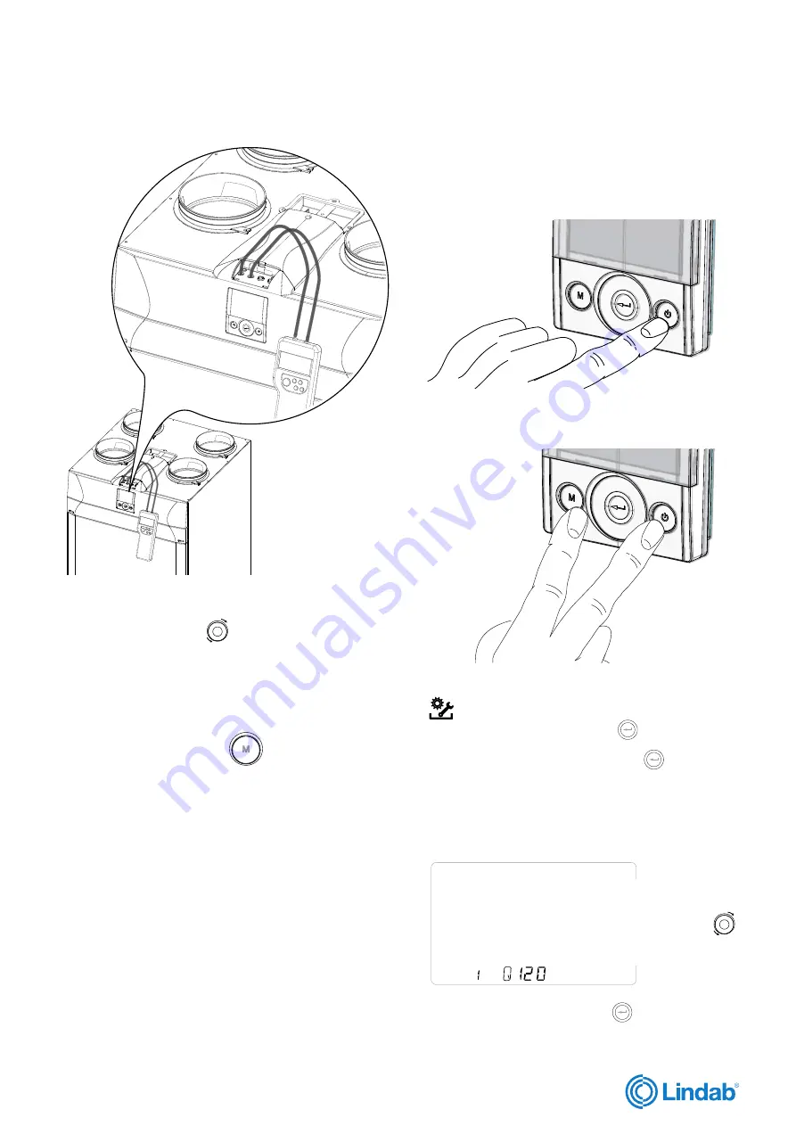
2. Press the ON/OFF and “M” Menu keys at the same time
to access the
TECHNICAL MENU
.
3. Use the
TOUCH PAD
to select the installer menu
.
Press the Enter key to confirm
Select the “
V
” symbol and confirm
The message V1 flashes;
Perform the setting of the fan V1;
access the menu by pressing enter, the display shows:
V
VV
set the nominal design
flow rate (m3/h) using
the
TOUCH PAD
+
_
.
Press the Enter key to confirm
Now proceed with connection of the differential pressure
switch to connections P1 and P2
“ V1 ” currently flashes on the control display;
use the
TOUCH PAD
to select fan “
V2
” and
confirm by pressing enter.
Carry out the procedure described above for V1 also
for fan V2.
When fan V2 has been set as well, go back to the
main screen by pressing “M”
3 times.
Disconnect the differential pressure gauge and put the
rubber caps and the cover of the front panel back in
place.
P1 P2
P3
P4
Lindab reserves the right to make changes without prior notice
202
2
-0
1
-
28
I
nstallation instructions
RHR-CF
lindab | we simplify construction
Fig. 41
14.4 Automatic calibration
ONLY WITH AUTOMATIC FLOW RATE CONTROL
SYSTEM INSTALLED
1.
Turn on the appliance by pressing the ON/OFF key on
the display.
Fig. 42
Fig. 43
Fig. 44
31


