background image


Linddana A/S

 . Ølholm Bygade 70 . DK-7160 Tørring . T +45 75 80 52 00 . tp@linddana.com www.linddana.com 


User instructions: TP 230 from 02.11.2015                                                                                              

©Copyright 2006 

11


6.3


Noise level 

 
The sound power level from the wood chipper has been measured during operation at 1000 rpm 
on the rotor disc, powered by a tractor. 
 
The measurements were performed according to testing regulations 
Directive 2000/14/EC, 3 July 2000 
EN ISO 3744, 1995 
ISO 11094, December 1993 
ISO 4871, 19 March 1997 
 
The warrantyd sound power level that must be disclosed by the manufacturer pursuant to 
directive 2000/14/EC is as follows: 
 

TP 230 wood chipper: 123 dB (A) re.1pW.


The above values take into account the common uncertainty of the measurement method and 
the estimated variation in a product range for the machine type. Detailed information on 
measurements and results and estimation of uncertainty can be found in an in-depth report, 
supplied on request. 
 
The sound level is such that hearing protection is mandatory during use. 


6.4


Environmental instructions 

 
When replacing hydraulic or motor oil, dispose of oil and oil and air filters in a responsible 
manner; take to an approved receiving station.  
 
Oil spills must be avoided as far as possible. In the event of a spillage, the spilled oil must be 
cleaned up and taken to an approved receiving station.  
 
Take worn-out parts for recycling. 
 
When the machine is no longer functional, it must be disposed of responsibly. Hydraulic and 
motor oil must be drained and taken to an approved receiving station together with oil and air 
filters. 
 
Take the rest of the machine for recycling of the materials. 

Summary of Contents for TP 230

Page 1: ...Linddana A S lholm Bygade 70 DK 7160 T rring T 45 75 80 52 00 tp linddana com www linddana com User instructions Spare parts catalogue for TP 230 wood chipper from the Forest series...

Page 2: ...and robot technology at light open production premises For safety reasons and in order to gain maximum benefit from your wood chipper it is essential to read through the user instructions before usin...

Page 3: ...nmark hereby declares that Wood chipper ________________________________________________ is in concordance with the provisions of the Machine Directive Directive 06 42 EF and with the national legisla...

Page 4: ...grams used 10 6 3 Noise level 11 6 4 Environmental instructions 11 7 Operation of the machine 12 7 1 Table 1 Rotation speed settings for feed rollers 13 8 Maintenance 13 8 1 Maintenance schedule 13 8...

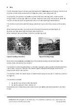
Page 5: ...in branches you must stand to the side of the feed funnel See Figure 1 Branches can whip about when the feed rollers catch them When feeding in logs push these in from the rear See Figure 2 Figure 1...

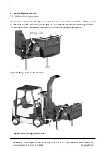
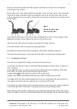
Page 6: ...1 Before initial operation The machine is equipped with a lifting eyelet that can be used when the machine is lifted by crane or other hoisting device hoisting See Figure 3 The machine can also be lif...

Page 7: ...draulic and motor oil and used oil and air filters to an approved receiving station 5 2 Coupling instructions The machine is designed for coupling to a tractor s three point hitch The factory can supp...

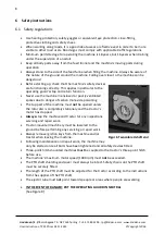
Page 8: ...return function Never use the machine in enclosed or poorly ventilated spaces due to danger of carbon monoxide poisoning The top part of the machine must not be opened unless the rotor disc is comple...

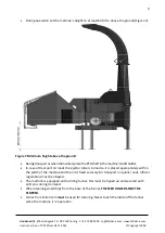
Page 9: ...s shaft holder In case of transport on roads the ejector tube is turned so it is placed appropriately within the width of the machine and then it is fixed securely For transport on public roads offic...

Page 10: ...s thrown Safety distance 20m Warning Rotating knives Wait for rotor to stop Warning Rotating rollers Warning Rotating belts Warning Danger of retraction Do not touch the hopper Warning Danger of retra...

Page 11: ...ent method and the estimated variation in a product range for the machine type Detailed information on measurements and results and estimation of uncertainty can be found in an in depth report supplie...

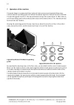
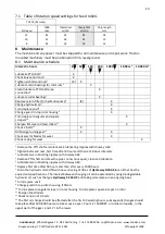
Page 12: ...B will reverse the oil flow in the control valve reverse the rollers and the material will now run out of the machine Figure 8 Feed funnel TP 230 with operating guard Figure 9 Directions for the oper...

Page 13: ...th Uniway Li62 2 Tighten bolts and nuts first time after 8 hours and then at 50 hour intervals 3 Lubricate two lubricating nipples with Uniway Li62 4 Remove PTO shaft and draw the pipe connections apa...

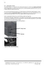
Page 14: ...ipper can be delivered factory filled with biodegradable oil of the type saturated ester Hydraway SE 46HP When replacing the oil use the same type of oil or oil with equivalent specifications Do not m...

Page 15: ...r reversible cutting edges What to do Stop the machine and turn off any power Remove the screen above the revolving roller Loosen the bolts holding the two sections of the rotor housing together and o...

Page 16: ...e inserting a new one clean the contact surface and the anvil carefully Set the anvil at 1 mm from the knives Use a feeler gauge Tighten the bolts for the vertical anvil to 200 Nm 20 KPm Once the anvi...

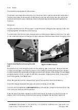
Page 17: ...from the knives when turning the rotor Figure 14 Locking the rotor using the rotor lock Figure 15 Knife measure Remove the four nuts holding the knife and the clamping plate to the rotor Remove the k...

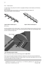
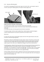
Page 18: ...r breaker type A Figure 17 Sliver breaker type B What to do Stop the machine and turn off any power Loosen the bolts holding the two sections of the rotor housing together and open the rotor housing R...

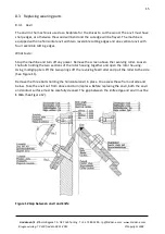
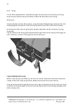
Page 19: ...blades on the rotor The rotor is now locked see Figure 14 Remove the countersunk bolts holding the square scraper in place on the rotor Turn the square so that a sharp corner points upwards Clean the...

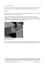
Page 20: ...ction of the rotor housing Remove the six bolts and nuts securing the casing to the bottom section of the rotor housing Figure 20 Tap the section of the casing protruding beyond the edge of the rotor...

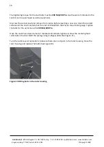
Page 21: ...ts holding the two sections of the rotor housing together and open the rotor housing Loosen the four bolts holding the hydraulic pump in place and adjust the tension using the adjusting screw Used bel...

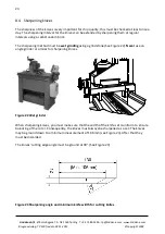
Page 22: ...dum brick The sharpening method must be wet grinding using a grindstone See Figure 22 Never use an angle grinder or similar for sharpening knives Figure 22 Wet grinder When sharpening knives you must...

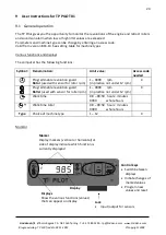
Page 23: ...e following functions Symbol Denomination Limit value Access code needed Programmable revolution guard Rotor used with sensor for rotor rpm 1 9999 rpm in practice not under 12 rpm X Programmable revol...

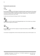
Page 24: ...onitor With each press on the key the position of the marker display indication changes one step The marker starts in the top left corner and then moves down The key is also used to leave the change m...

Page 25: ...ler exceeds upper limit value Roller blink display will alternately blink between 0 and 9999 Roller speed can be adjusted by adjusting the manual regulation of oil to hydraulic motors When roller spee...

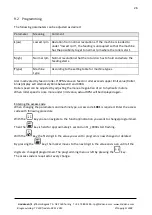
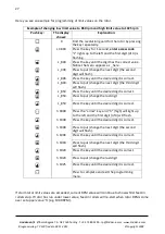
Page 26: ...e next digit the third digit will flash L _850 Press the key until the desired digit is correct L _85X Press to put change the last digit L _850 Press the key until the desired digit is correct h X000...

Page 27: ...Rotor RPM 8 mm 10 mm 13 mm TP230 PH 1000 54 67 81 Roller RPM for chip length required can be found on table above RPM value can be set using regulation screws on manoeuvre valve WORKING HOURS Display...

Page 28: ...erating hours can be reset at any time Press key until working time display appears Perform following key sequence Press key Display Explanation 72 57 example Find job hours by pressing key repeatedly...

Page 29: ...ddana com Brugsanvisning TP 230 fra dato 02 11 2015 Copyright 2008 30 9 3 Installation Mechanical setup and installation diagram Installation diagram using electronic sensors hall or inductive Rotor i...

Page 30: ...Technical data Display 6 digit Power supply 12 Vdc 1 24 A Temperature range TP Pilot is fully operational within 10 70 C Sensor pulse signals Max 225 pulse sec Note Control system monitor intended fo...

Page 31: ...l too poor The hydraulic filter is clogged The oil pump may be worn or damaged The oil motor is defective The pressure release valve in the control valve is clogged Unscrew the flow valve further open...

Page 32: ...the case of repair the purchaser is obliged to deliver and collect the sold item to from the workshop specified by Linddana at no cost to Linddana In the case of replacement of the defective part s t...

Page 33: ...rection will involve repair or replacement of the defective part s or will comply with the terms stated in point 4 Linddana is not liable in other respects for such defects This applies to any loss re...

Page 34: ...Rotor disc diameter mm 760 Rotation speed PTO rpm 1000 Number of knives 3 Power requirement min max kW HK 37 90 50 120 Max wood diameter mm 230 Chip length mm 10 18 Weight kg 990 Height mm 2950 Width...

Page 35: ...00 tp linddana com www linddana com Brugsanvisning TP 230 fra dato 02 11 2015 Copyright 2008 36 13 Hydraulic diagrams Figure 25 Hydraulic diagram for TP 230 without shaft speed monitor Figure 26 Hydr...

Page 36: ...om www linddana com Brugsanvisning TP 230 fra dato 02 11 2015 Copyright 2008 37 14 Accessories Tool kit incl torque wrench Prolonged ejector tube horizontal Extension for ejector tube vertical Sliver...

Reviews: