Service Training
Page
4
Section
2.3
2.3.2.1.1
REMOVING AND INSTALLING THE TORSION BAR SPRINGS
The number of torsion bar springs installed in the truck depends on the version of the cabin. When the cabin
is retrofitted to a different cabin version, the number of torsion bar springs must be changed, otherwise the
cabin will be too difficult to open or close too easily.
- Remove the electrical system cover.
- Dismantle the contactor support assembly and pull it aside until the spring pack is accessible.
- Open the cabin until the weight is full removed from the torsion bar springs (all springs are flat).
- Fix the overhead guard in this position with the aid of a crane and a sling.
- Remove the clamping plates on the right and left of the spring pack.
- Install the correct number of torsion bar springs.
- Install the correct fishplates and correct number of washers.
- Fasten fishplates at the left and right of the spring pack.
- Release the cabin from the crane.
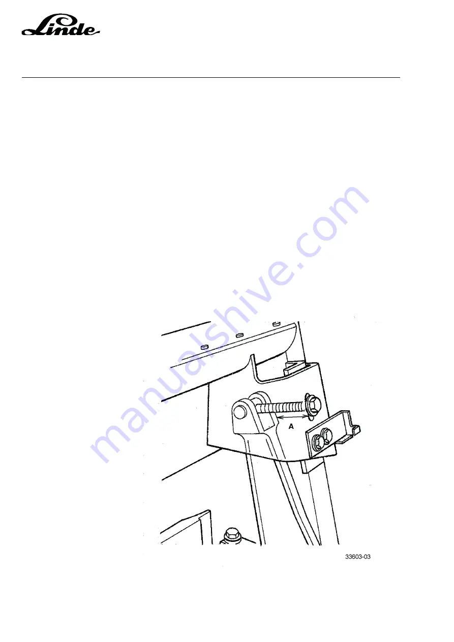
- A fine adjustment of the spring pack can be done with the adjusting screw on the tensioning lever on the
right-hand side of the cabin. Measure distance A for the adjustment.
NOTE:
Distance A is measured vertically from the rear edge of the lever to the inner edge of the roof
bracket.
Lever adjustment:
Cab Model
Distance A
1
40 mm
2
40 mm
3
35 mm
4
35 mm
5
25 mm
NOTE:
The cabin should be able to be opened and closed without too much effort.
Summary of Contents for 336 Series
Page 2: ......
Page 8: ...ServiceTraining ...
Page 12: ...ServiceTraining Section 2 1 Page 4 ...
Page 14: ...ServiceTraining Section 2 1 Page 6 2 1 4 TRACTIONMOTORDISASSEMBLY ...
Page 19: ...ServiceTraining Section 2 2 Page 3 ...
Page 21: ...ServiceTraining Section 2 2 Page 5 ...
Page 27: ...ServiceTraining Section 2 2 Page 11 ...
Page 28: ...ServiceTraining Section 2 2 Page 12 ...
Page 33: ...ServiceTraining Section 2 4 Page 1 2 4 STEERING SYSTEM ...
Page 35: ...ServiceTraining Section 2 4 Page 3 ...
Page 37: ...ServiceTraining Section 2 4 Page 5 ...
Page 39: ...ServiceTraining Section 2 4 Page 7 ...
Page 41: ...ServiceTraining Section 2 4 Page 9 ...
Page 45: ...ServiceTraining Section 2 4 Page 13 ...
Page 47: ...ServiceTraining Section 2 4 Page 15 ...
Page 53: ...ServiceTraining Section 2 5 Page 5 ...
Page 54: ...ServiceTraining Section 2 5 Page 6 ...
Page 69: ...ServiceTraining Section 2 6 Page 15 ...
Page 74: ...ServiceTraining Section 2 6 Page 20 2 6 2 3 CIRCUIT BREAKER CONTACTOR 1K6 Circuit diagram ...
Page 94: ...ServiceTraining Section 2 6 Page 40 ...
Page 111: ...ServiceTraining Section 2 6 Page 57 Connector 1X6 1 15 V 2 Output signal 3 ...
Page 126: ...ServiceTraining Section 2 6 Page 72 2 6 9 2 LOCATION OF CONNECTORS FROM SERIES 7 95 ...
Page 128: ...ServiceTraining Section 2 6 Page 74 ...
Page 145: ...Section 2 6 Page 91 ...
Page 146: ......
Page 147: ......
Page 149: ...Section 2 6 Page 93 ...
Page 150: ......
Page 153: ...ServiceTraining Section 2 7 Page 3 ...
Page 157: ...ServiceTraining Section 2 7 Page 7 ...
Page 158: ...ServiceTraining Section 2 7 Page 8 ...
Page 163: ...Section 2 9 Page 5 ...
Page 164: ......
Page 166: ...ServiceTraining Section 2 10 Page 2 ...
Page 167: ......


