Service Training
Section
2.6
Page
1
2.6
ELECTRICAL SYSTEM
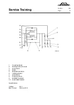
The series 336 trucks are equipped with a compact LTM control for the travel drive and the working hydraulic
system. The steering system is controlled via the lift LTM control.
The compact LTM control has the following advantages over the previous LTM control:
- less space required
- easier installation
- available as replacement part
- integrated freewheel diode
- integrated brake diode
- integrated regenerative braking diode
- easier troubleshooting
- improved dissipation of heat
Features of the power unit:
- N-type channel enhancement type MOSFET
- Zener diode for active overvoltage protection
- gate-source Zener diode and resistor against static overvoltage at the gate
- integrated gate resistors against internal oscillations
- insulated aluminium base plate
- longer air gaps
Regenerative braking is standard equipment for this series, which returns part of the energy generated during
braking back to the battery. The control unit and the fan are supplied with 24 V direct current via a separate
voltage converter.
Trucks equipped with optional lighting require a separate voltage converter.
Summary of Contents for 336 Series
Page 2: ......
Page 8: ...ServiceTraining ...
Page 12: ...ServiceTraining Section 2 1 Page 4 ...
Page 14: ...ServiceTraining Section 2 1 Page 6 2 1 4 TRACTIONMOTORDISASSEMBLY ...
Page 19: ...ServiceTraining Section 2 2 Page 3 ...
Page 21: ...ServiceTraining Section 2 2 Page 5 ...
Page 27: ...ServiceTraining Section 2 2 Page 11 ...
Page 28: ...ServiceTraining Section 2 2 Page 12 ...
Page 33: ...ServiceTraining Section 2 4 Page 1 2 4 STEERING SYSTEM ...
Page 35: ...ServiceTraining Section 2 4 Page 3 ...
Page 37: ...ServiceTraining Section 2 4 Page 5 ...
Page 39: ...ServiceTraining Section 2 4 Page 7 ...
Page 41: ...ServiceTraining Section 2 4 Page 9 ...
Page 45: ...ServiceTraining Section 2 4 Page 13 ...
Page 47: ...ServiceTraining Section 2 4 Page 15 ...
Page 53: ...ServiceTraining Section 2 5 Page 5 ...
Page 54: ...ServiceTraining Section 2 5 Page 6 ...
Page 69: ...ServiceTraining Section 2 6 Page 15 ...
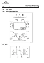
Page 74: ...ServiceTraining Section 2 6 Page 20 2 6 2 3 CIRCUIT BREAKER CONTACTOR 1K6 Circuit diagram ...
Page 94: ...ServiceTraining Section 2 6 Page 40 ...
Page 111: ...ServiceTraining Section 2 6 Page 57 Connector 1X6 1 15 V 2 Output signal 3 ...
Page 126: ...ServiceTraining Section 2 6 Page 72 2 6 9 2 LOCATION OF CONNECTORS FROM SERIES 7 95 ...
Page 128: ...ServiceTraining Section 2 6 Page 74 ...
Page 145: ...Section 2 6 Page 91 ...
Page 146: ......
Page 147: ......
Page 149: ...Section 2 6 Page 93 ...
Page 150: ......
Page 153: ...ServiceTraining Section 2 7 Page 3 ...
Page 157: ...ServiceTraining Section 2 7 Page 7 ...
Page 158: ...ServiceTraining Section 2 7 Page 8 ...
Page 163: ...Section 2 9 Page 5 ...
Page 164: ......
Page 166: ...ServiceTraining Section 2 10 Page 2 ...
Page 167: ......


