9/21
Linde AG, Linde Gas Deutschland ©
6.
DESCRIPTION OF THE APPLIANCE
MAIN PARTS
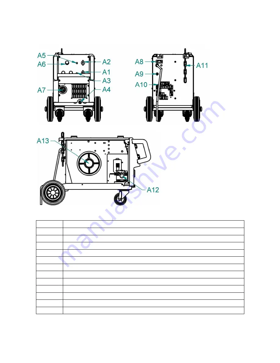
Fig. 1 - Main parts
A1
ON / OFF Switch
A2
Voltage switch
A3
LED ON Indicator
A4
Work leads
A5
LED over heating indicator
A6
Wire speed potentiometer
A7
EURO connector
A8
Gas heater connector
A9
Solenoid Valve – gas connector
A10
Mains cable
A11
Chain for fixing the gas cylinder
A12
Wire Feeder
A13
Spool Holder


