


LBON320AC Series 1.2 GHz Customer Premise RFoG ONU
Installation & Operation Manual
Page 2 of 4
OPTICAL, RF & POWER CONNECTIONS
1.
The powering port and all RF ports are standard F-type coaxial connectors. The optical connector is a SC/APC female-type.
2.
The LBON320AC can be powered with 12-15 VDC. It is recommended to power the LBON320AC using a 500 mA rated power pack at 12 VDC or 15 VDC output.
3.
Connect a coaxial cable from the output of the power pack to the PWR IN port on the LBON320AC.
4.
The LBON320AC can also be powered from the RF OUT/PWR IN port by combining RF and power via a power inserter.
5.
After connecting the coaxial cable between the power pack output and the LBON320AC, plug the power pack into the wall receptacle.
6.
When the LBON320AC powers up, the PWR LED will illuminate.
7.
Connect the LBON320AC chassis to physical earth (ground) by using the grounding screw on the LBON320AC.
8.
The LBON320AC accepts optical input of 1550 ± 10 nm and optical levels from -6 dBm to +2 dBm. Using an optical power meter, make sure the optical level on the
incoming fiber is within range.
9.
Make sure the optical cable is matched for the proper connector (ie. SC/APC to SC/APC). After cleaning all optical connectors, connect the optical fiber to the OPT
IN/OUT port on the ONU.
10.
If the optical power is within range, the OPT IN LED will illuminate. Once the optical fiber is connected to the ONU, the 1 mW/1 VDC test point (TP) can be used to
measure the optical input detected by the forward receiver in the ONU. Use a digital multimeter on DC voltage setting and measure between 1 mW/1V TP and the
grounding screw. See table below for relation between measured DC voltage on 1 mW/1V TP and optical power received by the RFoG ONU.
V (DC) on 1 mW/1 VDC
Test Point of ONU
Optical Level Hitting
the RX (mW)
Optical Level Hitting
the RX (dBm)
OPT IN
LED
1.58
1.58
2
ON
(1)
1.26
1.26
1
1.00
1.00
0
0.79
0.79
-1
0.63
0.63
-2
0.50
0.50
-3
0.40
0.40
-4
0.32
0.32
-5
0.25
0.25
-6
0.20
0.20
-7
ON
(2)
0.16
0.16
-8
0.13
0.13
-9
0.10
0.10
-10
< -10
OFF
(3)
NOTES:
(1)
Optical AGC
(2)
No optical AGC
(3)
Out of limit
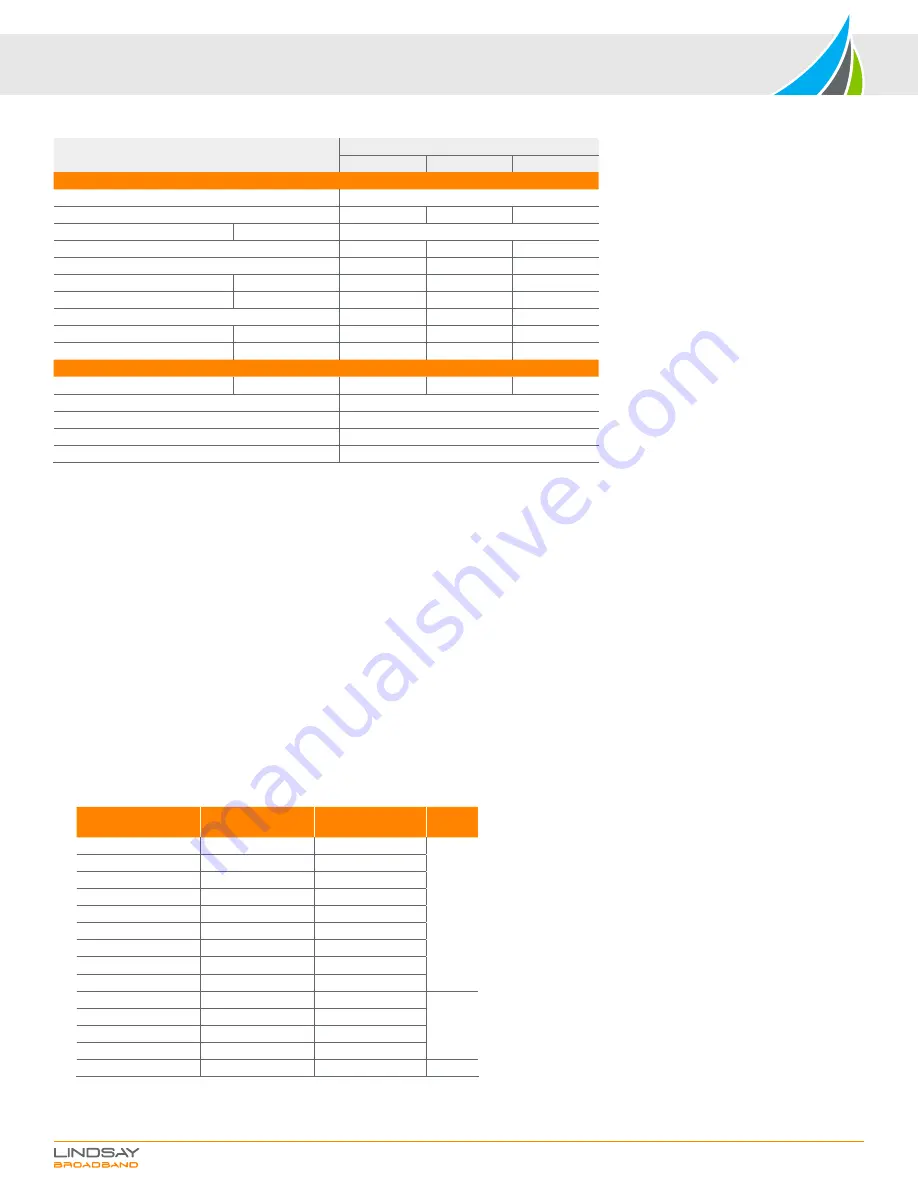
SPECIFICATIONS CONT'D.
Parameter
Specifications
Min
Typ
Max
Return Transmitter
Optical Wavelength
1310 nm, 1610 nm or CWDM
Optical Output Power
2 mW
3 mW
RF Input Level
Total power
20-40 dBmV
Dynamic Input Range
(3)
18 dB
Frequency Range (optional)
5 MHz
42 MHz
Flatness of Frequency Response
f = 5-42 MHz
± 0.75 dB
± 1 dB
Input Return Loss
f = 5-42 MHz
16 dB
Optical Output Return Loss
45 dB
Laser ON
± 1.5 dB
15 dBmV
Laser OFF
± 1.5 dB
-4 dBmV
Power, Environmental & Physical
Total Power Consumption
15 VDC power pack
≤ 4.2 W
Operating Humidity
5-95%, non-condensing
Operating Temperature
-40°C to +65°C (-40°F to +149°F)
Dimensions (H x W x D)
4.1”H x 6.7”W x 1.5”D (10.4H x 17.0W x 3.9D cm)
Weight
0.3 kg (0.7 lb)
NOTES:
(1)
Other diplex splits available: 65/85 MHz, 85/102 MHz & 204/256 MHz
(2)
-1 dBm optical input; 3.5% OMI/CH; 54-550 MHz analog channels & digital compressed channels above 550-1218
MHz at levels 6 dB below equivalent video
(3)
NPR at 30 dB. Measured using a receiver with an equivalent input noise (EIN) of <2.5 pA/Hz0.5 with a link budget
of 23 dB (20 km fiber + passive loss). NPR test performed with 37 MHz noise loading


