


LBON320AC Series 1.2 GHz Customer Premise RFoG ONU
Installation & Operation Manual
Page 3 of 4
OPTICAL, RF & POWER CONNECTIONS CONT'D.
FORWARD & REVERSE SETUP GUIDELINES
1.
Please note that there are no controls or adjustments on the LBON320AC. Do not open the lid. Opening the lid will void the warranty.
2.
For the forward path setup, make sure that the forward optical input level to the LBON320AC is within range as shown in the table in section OPTICAL, RF &
POWER CONNECTIONS above. If the optical input is higher than +2 dBm, receiver overload may occur. If the optical input is < -6 dBm, the LBON320AC loses
AGC tracking, RF output will not be as per specification, and the output will drop a further 2 dB with every 1 dB drop in optical input. The LBON320AC delivers
optimum performance at -1 dBm optical input level.
3.
The specified RF output levels are only guaranteed within optical AGC range and with OMI ≥ 3.5% on the 1550 nm downstream optical signal. To compensate for
RF cable losses, there is a 6 ± 1 dB slope on the RF output of LBON320AC from low frequency to high frequency.
4.
Connect a signal level meter at the RF OUT port to measure the RF output from the LBON320AC. You can also use the -20 dB TP to measure the RF output.
5.
Verify the RF output levels from the LBON320AC are as expected.
6.
This completes the forward path setup for the LBON320AC RFoG ONU.
7.
For the reverse path setup, make sure that the reverse input level to the LBON320AC is not too high or damage to the ONU may occur. The -20 dB TP is a
bi-directional test point and can also be used to inject the upstream test carrier. Compensate 20 dB if using the test point to inject the upstream test carrier.
8.
The upstream transmitter in the LBON320AC is a burst-mode transmitter and will only be activated if the RF input to the LBON320AC is within the upstream
frequency range (5-42 MHz or 5-85 MHz) and is higher than 15 dBmV ± 1 dB. When the transmitter is activated, the OPT OUT LED on the LBON320AC is
illuminated.
9.
The upstream RF input range for the LBON320AC is 15-35 dBmV per channel (digital channel level) for the 42/54 MHz LBON320AC, and 15-33 dBmV per
channel (digital channel level) for the 85/102 MHz LBON320AC. These upstream levels are assumed with the condition that a 42/54 MHz split unit will have 4
equally loaded channels in the upstream band, and the 85/102 MHz split will have 8 equally loaded channels in the upstream band. If using a different number of
channels from what is mentioned above, compensate for total RF power. The total RF input level to the LBON320AC (for all channels combined) should not exceed
more than 40 dBmV (digital channel level). More than 40 dBmV (digital channel level) total upstream RF input may cause laser clipping and saturation on the
LBON320AC. Use the following formula to calculate total RF power: Total RF power = RF power per c [10* log (# of channels)].
10.
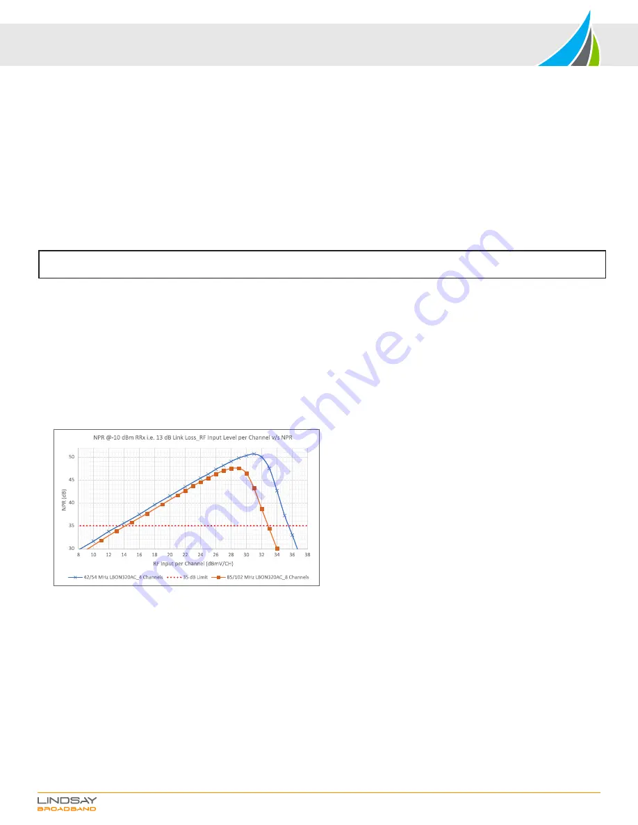
Refer to the NPR plot below to better understand the RF input levels to the LBON320AC.
11.
For optimum performance in the upstream direction, make sure the LBON320AC is operated with RF input levels to the left side of the NPR peak. Operating at
RF input levels to the left side of the NPR peak will provide the best MER/BER performance while assuring the laser saturation and clipping does not occur on the
RFoG ONU transmitter.
12.
This completes the reverse path setup for the LBON320AC RFoG ONU.
13.
If you have any more questions regarding the LBON320AC setup, please contact Lindsay Broadband for support.
NOTE: The RF levels mentioned in this manual are analog channel levels, unless specified. For digital channels assume 6 dB less to that of
analog channels.
11.
The F-port labelled “RF OUT” is the bi-directional RF input and output port for the LBON320AC RFoG ONU.
12.
The “TEST -20 dB” port is a bi-directional -20 dB TP that can be used to test RF input and output levels. When not in use, please terminate this -20 dB TP with a 75
ohm terminator.
13.
When using the -20 dB TP to measure the RF input/output levels, make sure the RF OUT port is terminated to 75 ohm. Please note the levels from -20 dB TP will
be 20 dB lower than the RF OUT port.
COMPLETING THE INSTALLATION
1.
Record the input and output levels for the station in both upstream and downstream for reference.
2.
Make sure the cables are routed properly and all connections are secured.
3.
Ensure the optical fiber cable is not pinched and does not have sharp bends.
TROUBLESHOOTING GUIDELINES
1.
No Power on the LBON320AC ONU.
a.
Check the powering coaxial cable and connections for intermittent connections.
b.
Check the output of the power adapter for proper DC voltage (12-15 VDC). It is normal for a linear power pack to have more than 15 VDC output when
unloaded. It should not be more than 20 VDC when unloaded. When the LBON320AC is connected to this unloaded power pack, the output voltage will drop
within 12-15 VDC specification.
c.
Check with a different 12 VDC or 15 VDC power pack that is at least rated for more than 500 mA.
d.
Try powering via the RF OUT/PWR IN port using a power inserter.


