User Manual
English
3
Package contents
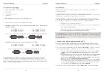
LINDY KVM Switch Classic 8/16 OSD
Power Adapter
19” Rackmount Kit
This manual
Optional Cables and Accessories (not included)
PS/2 to USB Converter Cable: LINDY No. 42866
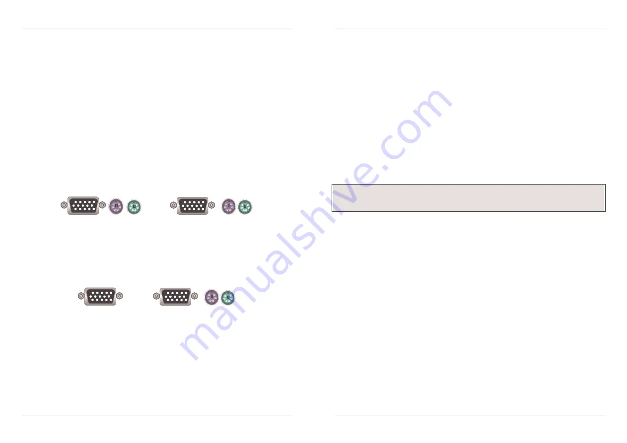
Combined (3-in-1) KVM Cable (For Classic 8 OSD server ports and Daisy Chain cable)
1m LINDY No. 33711
5m LINDY No. 33714
2m LINDY No. 33712
10m LINDY No. 33716
3m LINDY No. 33713
15m LINDY No. 33717
15 Way HD Male and 6 Pin Mini DIN Male to 15 Way HD Male and 6 Pin Mini DIN Male cables
Combined KVM Cable (For Classic 16 OSD server ports)
1m LINDY No. 32510
3m LINDY No. 32507
2m LINDY No. 32506
5m LINDY No. 32508
15 Way HD Male to 15 Way HD Male and 6 Pin Mini DIN Male special cables
Please Note: If some cables are not long enough we recommend that the complete cable is
replaced with a longer length rather than using extension cables. Extension cables introduce
additional plug to socket connections, which can adversely affect the signal quality. Please bear
this in mind when using high resolutions or long distances.
User Manual
English
4
Installation
Before you start please verify that all parts are included according to the package contents.
Please prepare the required amount of KVM cables to connect your computers/servers. If you
want to install the KVM Switch in a 19” server rack please attach the enclosed 19” Rackmount
brackets using the included screws.
In addition to the PCs/Servers to be connected you will need a PS/2 keyboard, monitor and
PS/2 mouse to use as a local console. You will also need combined 3-in-1 KVM connection
cables (as described on page 3) to connect the computers/Servers to the LINDY KVM Switch.
1. Switch off all the computers to be attached.
2. Connect the keyboard, monitor and mouse directly to the ports of the LINDY KVM
Switch labelled Console Port.
3. Now connect the servers and PCs to the ports labelled 1 to 8/16.
4. Attach the power supply to the KVM Switch. Switch on your monitor.
Cascading / Daisy Chaining of multiple KVM Switches
You can integrate up to 8 KVM Switches in one KVM daisy chained installation. Using the KVM
Switch Classic 16 OSD, this gives a maximum of 128 attached computers.
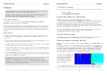
To connect an additional KVM Switch to the MASTER (or previous) KVM Switch use a standard
(VGA + 2 x PS/2) 3-in-1 KVM cable, with all male connectors.
1. First cascaded unit - Use a 3-in-1 KVM cable to connect the daisy chain port of the
MASTER KVM Switch to the console port of the first SLAVE KVM Switch.
2. Further cascaded units - Repeat the previous step to daisy chain more KVM
Switches. Each individual switch in the chain represents a different Bank. The
MASTER switch is Bank 1 and each cascaded SLAVE follows on as Bank 2, 3, 4
etc. to a maximum of eight banks/switches.
3. Resetting the Switches - After you have connected and switched on the SLAVE
KVM switches and computers, all of the KVM switches have to be reset. First, reset
the SLAVE KVM Switch at the end of the daisy chain and then reset all of the other
SLAVE switches up to the MASTER KVM switch.
To reset the switch, press the Bank and Scan button on the front panel of the switch.
Please Note:
Always plug in the power supply. Although the PCs connected to the KVM Switch
are able to supply enough power to the unit, the power adapter is needed to daisy chain more
KVM Switches. If you do not plug in the power adapter unexpected/erratic operation may occur.


