background image

English Manual 


LINDY KVM Extender C5 Pro   Installation and Use     

page 27 


If video compensation cannot solve the problem 

 
If automatic and manual compensation is unable to solve the problem, an additional module called a 
‘Skew Compensator’ may be required. Please see the next section for details. 
 

5.8 The Skew Compensator 
 

The twisted pair cabling supported by the Extender C5 set (category 5, or higher) consists of four 
pairs of cables. Three of these pairs are used by the modules to convey red, green and blue video 
signals to the remote video monitor. Due to the slight difference in twist rate between these three 
pairs, the red, green and blue video signals may not arrive at the monitor together. This is visible as 
seperate colour shadows on high contrast screen images. This effect is particularly apparent when 
using higher screen resolutions and some types of category 5e cables. In this situation, Lindy 
recommend the use of an optional module called the ‘Skew Compensator’ (Part No. 39389). This 
manually adjustable, passive device can apply fine timing changes to the video signals ensuring they 
arrive together thus removing the colour separation. The REMOTE module includes a skew report 
function that indicates how to set the multiple switches on the Skew Compensator. This report 
function can also be a useful tool in determining if a skew compensator is required.  


Summary of Contents for C5 Pro 39393

Page 1: ... LINDY ELECTRONICS LIMITED LINDY ELEKTRONIK GMBH FIRST EDITION August 2003 KVM Extender C5 Pro User Manual English LINDY Art No 39393 ...

Page 2: ...vices plugged into the wall outlet does not exceed the wall outlet s ampere rating Warranty information LINDY warrants that this product shall be free from defects in workmanship and materials for a period of three years from the date of original purchase If the product should fail to operate correctly in normal use during the warranty period LINDY will replace or repair it free of charge Any faul...

Page 3: ...a b Increase the separation between the equipment and the receiver c Connect the equipment to an outlet on a circuit different from that to which the receiver is connected d Consult the supplier or an experienced radio TV technician for help FCC Compliance Statement United States This equipment generates uses and can radiate radio frequency energy and if not installed and used properly that is in ...

Page 4: ...C5 module 12 3 Connections 13 Connections at the LOCAL module 13 3 1 KVM A multi cable connection 13 3 2 Serial cable connection 14 3 3 Twisted pair connection 14 Connections at the REMOTE module 15 3 4 Keyboard Video and Mouse connections 15 3 5 Twisted pair Power and Serial connections 15 3 6 Audio connections 16 4 Operation 18 4 1 Power and activity indicators 18 4 2 Locking and unlocking the s...

Page 5: ...nd Mouse restoration 23 5 7 Video compensation 25 5 8 Skew Compensator 27 5 9 Producing a Skew compensator report 28 5 10 Miscellaneous settings 29 6 Flash upgrade procedure 30 6 1 Downloading the upgrade files 30 6 2 Creating a startup disk 31 6 3 Reconfiguring the LOCAL connections 32 6 4 Reconfiguring the REMOTE connections 33 6 5 Returning all connections to their usual states 33 7 Troubleshoo...

Page 6: ...Y Extender C5 Pro set consists of two modules a local module that attaches to your computer system and a remote module to which the peripherals are connected The long distance link between the two modules is made via Category 5 or higher twisted pair cabling Internal circuitry within the remote module ensures crisp video images by automatically compensating for the length of the twisted pair cable...

Page 7: ...English Manual LINDY KVM Extender C5 Pro Installation and Use page 7 1 1 Supplied items ...

Page 8: ...English Manual LINDY KVM Extender C5 Pro Installation and Use page 8 ...

Page 9: ...er is on or off the only exception to this rule is switch 1 of the LOCAL module which initiates slightly different functions depending on the power state when it is switched LOCAL Switch 1 OFF Normal operation ON Before power is applied Places the LOCAL module into flash upgrade mode so that the internal software can be changed See section 6 Flash upgrade procedure ON Whilst power is applied Place...

Page 10: ... attempting to interpret them LOCAL Switch 3 OFF Microphone input on REMOTE module Use this setting if a standard mono channel microphone is connected to the microphone input on the REMOTE unit ON Stereo line in input on REMOTE module Use this setting if a stereo input is applied to the microphone input on the REMOTE unit LOCAL Switch 4 OFF Normal operation ON Suspend operation and reset the LOCAL...

Page 11: ...ed is a special configuration command for the module and is not to be passed to the computer system 2 OFF Hotkeys CTRL and SHIFT 3 OFF 2 OFF Hotkeys ALT and SHIFT 3 ON 2 ON Hotkeys CTRL and ALT 3 OFF 2 ON Hotkeys disabled 3 ON REMOTE Switch 4 OFF Automatic video compensation mode In this mode circuitry within the REMOTE module will adjust the video compensation settings automatically at power on t...

Page 12: ...d secure it with the two countersunk screws 2 Orientate the module on its side so that its labelled face is the correct way up and the securing plate is facing away from the rack 3 Slide the module into the required rack position The rectangular cut out in the front upper lip of the rack allows the two screws on the module s upper edge to slide through 4 The rack mount chassis has a series of hole...

Page 13: ...module are made via the supplied multi cable This has a single connection to the module is two metres in length and splits out to the keyboard video mouse microphone and speaker ports of the system 1 Attach the supplied KVM A multi cable to the 25 way socket at the end of the LOCAL module 2 At the other end of the KVM A cable attach the keyboard mouse and video microphone and speaker connectors to...

Page 14: ... and your computer system use the supplied serial link cable 1 Attach the male connector of the serial link cable to the 9 pin port on the LOCAL module 2 Connect the other end of the serial link cable to the appropriate serial port of the computer system 3 3 Twisted pair connection The link between the LOCAL and REMOTE modules is made via twisted pair cable specified to Category 5 or higher Ensure...

Page 15: ...EMOTE module 3 Insert the keyboard lead into the green mini DIN socket on the REMOTE module 3 5 Twisted pair power and serial connections 1 Insert the connector from the twisted pair cable link into the socket 2 Attach the output connector of the power supply to the socket at the front edge of the REMOTE module 3 Insert the IEC connector of the supplied power lead into the corresponding socket of ...

Page 16: ...r support a mono channel microphone or alternatively receive stereo line input Switch 3 on the LOCAL module controls the setting of this port LOCAL switch 3 OFF microphone LOCAL switch 3 ON stereo line in 1 Connect the microphone or stereo line input plug into the REMOTE module microphone socket Note Ensure that the setting of switch 3 on the LOCAL module matches the input to this socket OFF micro...

Page 17: ...ge 17 Note When the REMOTE module is rack mounted the audio connections must be made after the module has been fixed in place Access is required to the rear and above the rack Remember to remove the audio connections before attempting to slide out the REMOTE module ...

Page 18: ...for the LOCAL module the keyboard connection from the module for one second and then reconnect General Use In use the Extender C5 modules should be transparent the system and its peripherals should operate exactly as normal the only difference being that they are now up to 200 metres apart In some installations you may see some shadows to the right of high contrast screen characters This is caused...

Page 19: ... screen will go blank and the three keyboard indicators will begin alternately flashing between the Num Lock and Scroll Lock and Caps Lock This sequence indicates that a password is required To unlock the system 1 Enter the correct password and press f Note Passwords are NOT case sensitive Note If an invalid password has been entered and the keyboard indicators are not flashing as described above ...

Page 20: ...nsation allows you to manually adjust the video compensation settings Miscellaneous functions 5 2 What are hotkeys Hotkeys are two normal keyboard keys that when pressed simultaneously with a third key signal to the Extender C5 modules that you are sending a message specifically to them and not to the computer The hotkeys are ordinarily b and j while the third key determines what you want the modu...

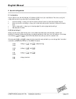
Page 21: ... three keyboard indicators will illuminate continuously 3 Press the number of the required configuration option for instance 8 The Scroll Lock indicator will extinguish leaving the Num Lock and Caps Lock indicators lit 4 Press f to confirm your option The three keyboard indicators Num Lock Caps Lock and Scroll Lock will now begin to flash in sequence again To exit from the configuration mode 1 Wit...

Page 22: ...ock the system using your password please see section 4 2 Locking and unlocking the system 5 5 Password override This mode allows you to override the password that has been set at the REMOTE module and place it into configuration mode so that a new one may be set This feature is particularly useful when passwords have been lost or forgotten To override the REMOTE password 1 Remove power from the R...

Page 23: ...gged the Extender C5 modules The previous setting depends both on the type of mouse and the type of driver as various combinations of PS 2 and IntelliMouse are possible Using the incorrect restore function may produce unpredictable results and require the system to be rebooted Which restore setting do I use The general rule is that unless both the mouse and the driver are both IntelliMouse compati...

Page 24: ...tion that the chosen restore function is incorrect Try again using the other restore function Note The restore functions predict the likely mouse resolution settings but may not restore the exact speed or sensitivity settings that were originally set Microsoft and Logitech specific mouse settings In certain installations some Logitech mouse drivers may lose the action of the mouse buttons when use...

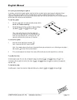
Page 25: ...n circumstances you may wish to finely adjust and fix the compensation level to suit personal preferences this can be done by switching to manual compensation mode To display a suitable high contrast image The best way to clearly view the effects of compensation is to display a high contrast image with vertical edges on the screen Open a word processor type the capital letter H or M and increase t...

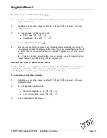
Page 26: ...tomatic compensation level you can use this as a starting point for your fine tuning Press w to increase compensation by one fine step Press to increase compensation by one coarse step Press g to select the neutral setting no compensation Press to decrease compensation by one coarse step Press y to decrease compensation by one fine step Note If the monitor goes blank and switches off due to extrem...

Page 27: ...ist rate between these three pairs the red green and blue video signals may not arrive at the monitor together This is visible as seperate colour shadows on high contrast screen images This effect is particularly apparent when using higher screen resolutions and some types of category 5e cables In this situation Lindy recommend the use of an optional module called the Skew Compensator Part No 3938...

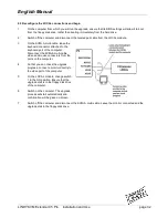
Page 28: ...ritten to the application by generating a series of faked key presses 3 Simultaneously press the hotkeys by default b and j along with f to enter configuration mode 4 Enter one of the following codes depending on the type of keyboard being used QWERTY keyboard i e English German press F 3 AZERTY keyboard French press F 4 The screen will go blank for a few seconds whilst the measurements are made W...

Page 29: ...iating this command ensure that the system is running an application that can display typed keys as screen characters e g a word processor or Windows Notepad The current firmware version will be written to the application in the form of the letter V followed by three numbers for example V118 means version 1 18 Reset all configuration options to default states F 8 f Returns all user configurable op...

Page 30: ...need to perform the following stages Download upgrade files from the LINDY website Create a startup diskette and copy the files to it Reconfigure the LOCAL module connections and begin Reconfigure the REMOTE module connections and begin Return all connections to their usual states 6 1 Download the upgrade files To download the files 1 Access the LINDY Electronics Ltd website www lindy com enter th...

Page 31: ...ontrol Panel 3 Double click on the Add Remove Programs icon 4 Select the Startup Disk tab 5 Click Create Disk and follow the instructions To create a startup disk in Windows 95 98 alternative method 1 Insert a disk into the floppy disk drive 2 Right mouse click on the 3 Floppy A icon and select Format 3 Select the Full format option and ensure that the Copy system files box is checked 4 Select Sta...

Page 32: ...rd connector attached to the keyboard port of the computer Disconnect the KVM A multi cable video and mouse connectors from the ports on the computer 4 So that you can check the upgrade progress connect a monitor directly to the video port of the computer 5 On the LOCAL module change switch 1 to the ON position Ensure that the upgrade disk is in the floppy disk drive of the computer 6 Switch on th...

Page 33: ...f the REMOTE module and connect the mains lead to a nearby wall socket 5 Switch on the computer The upgrade process will start automatically and confirmation will be given on screen 6 Switch off the computer and disconnect the REMOTE module Return REMOTE switch 1 to the OFF position 6 5 Return all connections to their usual states Once the upgrade process has been completed perform the following t...

Page 34: ... keys are pressed or the mouse is moved check that the indicators flicker if they do not then there could be a twisted pair link problem or a problem with one of the modules Check that the Category 5 or higher cable is wired correctly as per the diagram in the section 5 8 Skew Compensator If possible try using an alternative twisted pair connection between the modules If the REMOTE module is sever...

Page 35: ...et Check the setting of LOCAL switch 3 if a microphone is connected at the REMOTE module the switch should be set to OFF Sound input from the stereo line input is distorted and only one channel is working Check the setting of LOCAL switch 3 if a stereo line input is connected at the REMOTE module the switch should be set to ON ...

Page 36: ...ns LINDY C5 Series Rack mount chassis Part No 39388 This 19 chassis allows multiple C5 Series modules to be neatly arranged within a standard cabinet Securing plates and screws are supplied separately LINDY C5 Series Power distribution module Part No 39386 Provides power for up to four C5 Series modules to reduce mains power socket requirements LINDY C5 Series Rack mount securing plates For Extend...

Reviews: