V. General Specifications
II. Operation Procedure
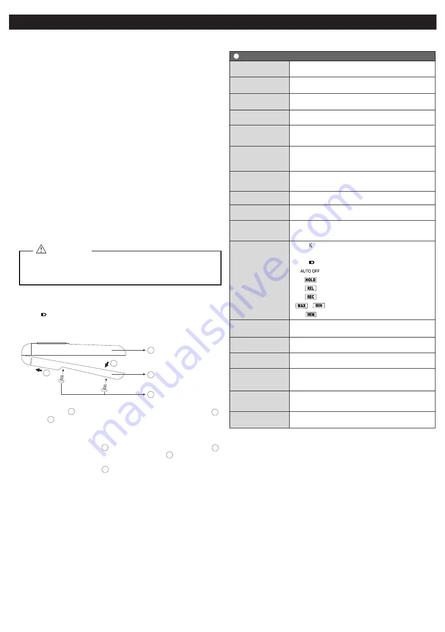
III. Battery Replacement
DIGITAL THERMOMETER MANUAL
TC-400A
If the " " indicator is displayed, it indicates a Low Battery condition and
the battery needs to be replaced. Please follow carefully the procedure
below for replacing battery.
IV. Storage and Cleaning
1. Unscrew Screw , and then open the unit by pulling the Lower-Cover
in arrow direction.
2. Remove the battery on the printed circuit board.
3. Replace the battery with new one. Make sure the battery is properly
connected to the terminals.
4. Place back the Lower-Cover by inserting its front end first on arrow
direction and then push it closely to the Upper-Cover until it snaps.
5. Make sure the rubber gasket is properly located when the unit is closed.
6. Lock the unit with the Screw .
· Use only suitable battery written on the specification.
· Do not dispose battery on household waste, fire or water.
· Remove the battery when the device will not be used for long period of
time.
· The instrument cannot measure accurately after low battery indicator is
displayed. Please replace the battery immediately.
1.) Connect the probe to the instrument through the Input Connector
· Probe can be checked if properly connected with the Burn Out feature
of this instrument.
2.) Turn the power ON.
· Upon turning ON the instrument, all the display and indicators will light
up for several seconds. This is to check if all segments of the display are
working properly. Afterwards, it will shift to its normal operating mode
with the following default items and features.
> Set at measuring mode.
> Unit set at °C.
> Thermocouple type indicator is displayed.
> Auto-Power Off indicator is displayed.
> Other indicators are not displayed.
· Auto-Power Off function is automatically enabled upon turning ON the
instrument (Please see Function list on how to disable).
· If the burnout display (----) is shown, the probe is not inserted properly.
In this case, check the probe side.
3.) Attach the sensor part of the thermocouple probe to the object you want
to measure.
· Wait until the measured value becomes stable.
· For long time measurement, use Recording function to avoid the
sudden turned Off of the instrument due to Auto-Power Off function.
4.) Turn OFF the instrument after using.
· After every use, always turn OFF the instrument.
Approx. 0.5 sec.
Digital Linearize
°C/°F, Auto-Power Off, Data Hold, Data Record
(Max/Min/Memory), Relative Measurement
Thermocouple Type
Burn-out
Low Battery
Auto-Power Off
Data Hold
Relative Measurement
Max / Min Data Recording
Max / Min Data Memory
Recorded Memory Data
0 - 50
°
C ( 32 - 122°F)
0 - 90%RH (Non-condensing)
006P (9V) Battery
Approx. 500 Hours (Manganese Battery use)
Approx. 166(H) x 68(W) x 35(D)mm
Approx. 200g
Thermocouple Connector
MODEL
NO. OF INPUT
SENSOR TYPE
MEASURING
RANGE
SAMPLING TIME
TEMPERATURE
COEFFICIENT
LINEARIZE
METHOD
DISPLAY
SENSOR
CONNECTOR
FUNCTIONS
POWER SUPPLY
BATTERY LIFE
OPERATING
TEMP./HUMIDITY
SIZE / WEIGHT
TC-400A
1
Thermocouple Probe Type K
-160°C - +1,372°C (-256°F - +2,502°F)
RESOLUTION
ACCURACY
at 25°C(77°F) ±5°C(9°F)
0 - 199.9°C (32°F - 391.8°F) : ±(0.1% of r 0.7°C(1.3°F))
-0.1°C(31.8°F) or less : ±(0.2% of r 1°C(1.8°F))
200°C(392°F) above : ±(0.2% of r 1°C(1.8°F))
±(0.015% of r 0.06°C) / °C
±(0.015% of r 0.108°F) / °F
Main Unit
The keys of this instrument can be switched with only a slight pressure.
Make sure that the instrument is not mistakenly set to a state other than
that intended.
ATTENTION
· Storage Temperature: -10 - +50°C (14 - 122°F)
· Storage Humidity: Less than 85% RH.
· When storing the instrument, avoid the following locations where:
1. Humidity is high.
2. The instrument is exposed to direct sunlight.
3. The instrument is exposed to a extreme temperature.
4. Large vibration exist.
5. Dust, salt, and/or corrosive gas exist.
· Keep the instrument clean at all times.
· Wipe off stains using a moist and soft cloth. Do not use any cleaning
agents or solvents.
VI. Accessories (Sold Separately)
- Carrying Case (HM-818)
- Thermocouple Probes (See catalog for probes)
1
Upper-Cover
Lower-Cover
Screw
1
2
3
----
CE and RoHS
COMPLIANCE
2
A
B
A
2
B
3
1
This manual was last revised May. 23, 2017. 4TC018C
*Subject to change without prior notice.
All Rights Reserved,Copyright © 2017,LINE SEIKI CO.,LTD.
199.9°C (391.8
°F) and below : 0.1°C (0.2°F)
200°C (392
°F) and above : 1°C (2°F)


