76
DO986BFK
IT
· La spina è l’unico modo per scollegare l’apparecchio dall’alimentazione
di rete. Pertanto assicurarsi che la spina sia sempre facilmente
raggiungibile. Per scollegare l’alimentazione verso l’apparecchio,
spegnere quest’ultimo poi estrarre la spina dalla presa.
· L’apparecchio deve essere collegato a una messa a terra. Il produttore
non è responsabile per danni causati dal mancato utilizzo della messa a
terra.
·
Una volta installato l’apparecchio, attendere 8 ore prima di accenderlo.
In questo modo si garantisce il posizionamento del refrigerante.
· Lasciare l’apparecchio acceso vuoto per 24 ore in modo che l’interno si
raffreddi raggiungendo la temperatura appropriata.
· L’apparecchio è progettato per funzionare a una temperatura ambiente
compresa tra 16 °C e 38 °C. L’apparecchio non funzionerà correttamente
in un ambiente con temperatura inferiore o superiore.
· L’apparecchio può essere utilizzato solo in ambienti chiusi.
·
Il congelatore emette del rumore quando il compressore fa circolare il
refrigerante. Questo è normale.
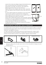
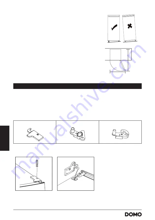
INVERSIONE DELL’APERTURA DELLO SPORTELLO
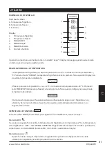
Se si desidera spostare dal lato opposto le cerniere dello sportello, è consigliato contattare un riparatore
autorizzato per fare eseguire il lavoro. Prima di invertire l’apertura, controllare che la spina sia rimossa
dalla presa e che l’apparecchio sia vuoto.
Una volta invertita l’apertura, attendere 8 ore prima di accendere l’apparecchio. In questo modo si
garantisce il posizionamento del refrigerante. Si consiglia di usare un cacciavite a punta piatta, un
cacciavite con punta a stella e una chiave (non forniti) oltre ai seguenti componenti forniti.
Piastrina di copertura per cerniera
,QVWDOODWLRQ
Left Aid-Closer on Upper Door x 1 Left Aid-Closer on Lower Door x 1
nscrew top hinge cover and disconnect connectors of door switch and harness.
2.Unscrew top hinge
3.Remove the pin with a screwdriver and filp the hinge bracket. Then refit the pin to hinge bracket
screw
screw
Stop sportello superiore
,QVWDOODWLRQ
Left Aid-Closer on Upper Door x 1 Left Aid-Closer on Lower Door x 1
nscrew top hinge cover and disconnect connectors of door switch and harness.
2.Unscrew top hinge
3.Remove the pin with a screwdriver and filp the hinge bracket. Then refit the pin to hinge bracket
screw
screw
8
Stop sportello inferiore
,QVWDOODWLRQ
Left Aid-Closer on Upper Door x 1 Left Aid-Closer on Lower Door x 1
nscrew top hinge cover and disconnect connectors of door switch and harness.
2.Unscrew top hinge
3.Remove the pin with a screwdriver and filp the hinge bracket. Then refit the pin to hinge bracket
screw
screw
8
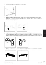
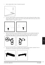
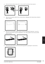
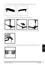
1.
Svitare le viti della piastrina di copertura per cerniera e rimuovere la piastrina. Scollegare entrambi i
connettori dei cavi.
,QVWDOODWLRQ
Left Aid-Closer on Upper Door x 1 Left Aid-Closer on Lower Door x 1
nscrew top hinge cover and disconnect connectors of door switch and harness.
2.Unscrew top hinge
3.Remove the pin with a screwdriver and filp the hinge bracket. Then refit the pin to hinge bracket
screw
screw
8
y
y
,QVWDOODWLRQ
1007
NN
1071
NN
6SDFH5HTXLUHPHQW
Keep enough space of door open.
Keep at least 50mm gap at two sides.
To do this adjust the two levelling feet at front of the unit.
If the unit is not level, the doors and magnetic seal
alignments will not be covered properly.
/HYHOOLQJWKHXQLW
y
y
,QVWDOODWLRQ
1007
NN
1071
NN
6SDFH5HTXLUHPHQW
Keep enough space of door open.
Keep at least 50mm gap at two sides.
To do this adjust the two levelling feet at front of the unit.
If the unit is not level, the doors and magnetic seal
alignments will not be covered properly.
/HYHOOLQJWKHXQLW
13
Summary of Contents for DOMO DO986BFK
Page 114: ...114 DO986BFK ...
Page 115: ...115 DO986BFK www domo elektro be ...


