background image

AERO.100 User Guide    


©2016 TLS Corp.   ALL RIGHTS RESERVED


Oct 2016 


Page 27 


an IP address that is in the subnet with the AERO’s IP address.  A crossover cable is not needed 
for this. 

4.2

4.2

4.2

4.2


Using NfRemote

Using NfRemote

Using NfRemote

Using NfRemote    

After successful connection, Nfremote starts at the Home Screen.  The NfRemote interface 
screen is fully re-sizeable and can be adjusted in the same manner as any MS Windows app 
screen.  That is, via handles at each corner.  The displays and windows will dynamically adjust 
themselves to make the best use of available screen real estate as you resize the window. 

The first time NfRemote starts it is in Tree navigation mode.  Tree navigation works in the same 
way that front panel navigation works.  Each time you click a menu item it opens the next menu 
level and so on down through the menus.  ‘Breadcrumbs’ are shown in the space below the 
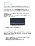
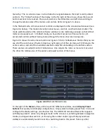
meters.  Home is shown at left below the meters.  See Figure 4-4. 


                                          Figure 4-4 

Home screen, Tree mode (default) 

At the top of NfRemote are displays that indicate the AERO.100’s CPU load, client volume 
(streaming audio), headphone volume, and the host PC’s CPU load.  See Figure 4-4.  In some 
cases, when the display is made smaller, these controls combine and a drop-down arrow 
appears allowing you to activate individual controls.  


Summary of Contents for AERO.100

Page 1: ...AERO 100 Audio Loudness Manager User Guide Release date November 2016 v4 Software Version 3 15 26 and later Linear Acoustic Phone 717 735 3611 Fax 717 735 3612 Web www linearacoustic com L16 18152...

Page 2: ...2 8 Updates 12 2 9 Feedback 12 2 10 Service 12 2 11 Support 12 2 12 Register Your Product 13 3 Introduction to AERO 100 14 3 1 Definitions and Abbreviations 14 3 2 AERO 100 Basics 15 3 3 Back Panel 17...

Page 3: ...Delay 45 4 10 8 Audio Delay 46 4 11 Dolby Encoding 47 4 12 Dolby Decoding 49 4 13 UPMAX 50 4 13 1 Enable and Configure UPMAX 50 4 13 2 UPMAX Operating Modes 51 4 13 3 Adjusting the Upmix 52 4 14 UPMA...

Page 4: ...9 6 4 Dolby Insert 80 6 5 Dolby Encoding of Instance 1 SAP using Instance 2 Dolby Encoder 81 6 6 Auto Replace of Stereo Program by 5 1 Surround Program 81 6 7 Low Latency Mode 83 7 Troubleshooting 84...

Page 5: ...AERO 100 User Guide 2016 TLS Corp ALL RIGHTS RESERVED Oct 2016 Page 4...

Page 6: ...WARRANTY PLEASE SAVE THE SHIPPING CARTON AND ALL PACKING MATERIALS FAILURE TO RETURN UNIT IN ORIGINAL SHIPPING CARTON AND PACKING MATERIALS WILL RESULT IN A CHARGE FOR NEW SHIPPING MATERIALS LIMITATI...

Page 7: ...Linear Acoustic the LA symbol UPMAX AEROMAX AERO 100 AERO air AutoNorm MetaMAX AutoMAX II AutoVoiceover AutoVOX AutoSAP and CrowdControl are trademarks or registered trademarks of Linear Acoustic Inc...

Page 8: ...cause harmful interference in which case the user will be required to correct the interference at his or her own expense 2 2 2 2 2 2 2 2 Canada Canada Canada Canada This Class A digital apparatus com...

Page 9: ...MENT OF THE UNIT ENSURE FUSES FITTED ARE THE CORRECT RATING AND TYPE AS MARKED ON THE U NIT THE UNIT MUST BE EARTHED BY CONNECTING TO A CORRECTLY WIRED AND EARTHED POWER OUTLET THE POWER CORD SUPPLIED...

Page 10: ...A UNIDAD NO DEBE SER EXPUESTA A GOTEOS O EXPUESTA A GOTEOS O EXPUESTA A GOTEOS O EXPUESTA A GOTEOS O SALPICADURAS Y N O D SALPICADURAS Y N O D SALPICADURAS Y N O D SALPICADURAS Y N O DEBEN COLOCARSE...

Page 11: ...D TE VERMIJDEN VERMIJDEN VERMIJDEN VERMIJDEN DIENEN DE VOLGENDE DIENEN DE VOLGENDE DIENEN DE VOLGENDE DIENEN DE VOLGENDE REGELS IN ACHT TE WO REGELS IN ACHT TE WO REGELS IN ACHT TE WO REGELS IN ACHT T...

Page 12: ...n the following steps are performed Ensure that the main power cable to the unit is not connected to a power source 1 Open the fuse compartment door in the AC power input housing with a small flat bla...

Page 13: ...evisions or new products Please contact us with your comments 2 10 2 10 2 10 2 10 Service Service Service Service You must contact Linear Acoustic before returning any equipment for factory service We...

Page 14: ...ormation which may be useful for product selection and support The URL is www linearacoustic com 2 12 2 12 2 12 2 12 R R R Register Your Product egister Your Product egister Your Product egister Your...

Page 15: ...Instance is capable of processing three stereo programs One source can be 5 1 or mixed 5 1 and stereo The 5 1 source will be downmixed AMX2 0 is also referred to as 2 2 2 or in some references as 2 2...

Page 16: ...signal This is an AES digital audio signal and can be silent or contain audio A timing reference is derived from the AES signal s timing This is NOT word clock DVS is descriptive video service SAP is...

Page 17: ...er format The AERO 100 s features include Program configurations any combination of two AMX5 1 5 1 2 2 AMX2 0 2 2 2 or AMX5x2 2 2 2 2 2 processing engines with support for local input on the last ster...

Page 18: ...AERO 100 back panel Its connector functions are described below from left to right Analog I O DB9F not used Metadata I O DB9F RS 485 metadata no crossover cable required Reserved RJ45 Reserved for fu...

Page 19: ...e 2016 TLS Corp ALL RIGHTS RESERVED Oct 2016 Page 18 AES I O DB25 4 AES audio pairs GPI O DB25 Eight parallel inputs 5 V TTL levels active low PSU1 PSU2 AC power inlets Note All BNC inputs are 75 inte...

Page 20: ...e t e r Dolby Encode Delay Delay Proc 1 2 Proc 3 4 Proc 5 6 Proc 7 8 Proc 9 10 Local Delay Delay M e t e r M e t e r Output Routing Proc Out 1 2 Proc Out 3 4 Proc Out 5 6 Proc Out 7 8 Proc Out 9 10 HD...

Page 21: ...oc Out 7 8 Proc Out 9 10 HD SD SDI HD SD SDI Dolby Enc Out AES Out Pairs 1 to 4 This symbol indicates a software audio switch to control what audio program is applied to the output of the block or con...

Page 22: ...c 7 8 Proc 9 10 Local Delay Delay M e t e r M e t e r Output Routing Proc Out 1 2 Proc Out 7 8 Proc Out 9 10 HD SD SDI HD SD SDI Dolby Enc AES Out Pairs 1 to 4 This symbol indicates a software audio s...

Page 23: ...n the SDI source Knowledge of where the loudness controlled audio program s need to be embedded in the SDI output Having this information will allow you to configure the unit for use as you learn to n...

Page 24: ...wo power supplies dual redundant internal PSUs Always connect BOTH power inlets to clean AC power sources ideally from separate AC power feeds Remember this is primarily to protect you against unrelia...

Page 25: ...several points internal to the loudness controller Presets System I O setup main upmix local upmix loudness control can each be saved to the host PC and restored from the host PC The entire AERO 100 c...

Page 26: ...ad it from www linearacoustic com Place NfRemote exe on your desktop Click on NfRemote exe to launch the installer and select Install from the menu See Figure 4 1 Figure 4 1 Remote software installer...

Page 27: ...NfREmote connection screen If NfRemote fails to connect make sure that the IP address shown on the unit s front panel is the one entered in NfRemote and ensure that your PC is in the same subnet and h...

Page 28: ...use of available screen real estate as you resize the window The first time NfRemote starts it is in Tree navigation mode Tree navigation works in the same way that front panel navigation works Each...

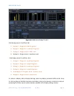
Page 29: ...meter window and left click to return to the NfRemote configuration screen Figure 4 5 Menu drop down selections Note that the menu buttons below the meters show where you are in the menu Home System I...

Page 30: ...u structure in sequence Figure 4 6 shows the same menu location as Figure 4 5 but in Tabbed view Notice that you can see all of the sub menus of System top row right side all of the sub menus of I O S...

Page 31: ...ll always find the AERO 100 at the same IP address To enter a static IP address Starting from the Tabbed NfRemote display select 1 System Network Access IP Configuration 2 If the Use DHCP button is li...

Page 32: ...ature allows automation scheduling and maintenance computers to access the AERO while computers not in the white list cannot access the unit An additional security measure is that the AERO will not re...

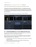
Page 33: ...ess Example 192 168 1 Figure 4 8 HTTP access 4 5 4 5 4 5 4 5 Downloading NfRemote From the AERO 100 HTTP server Downloading NfRemote From the AERO 100 HTTP server Downloading NfRemote From the AERO 10...

Page 34: ...rd keep it in a safe place If the password is lost or removed the unit must be sent back to the factory to regain control of the unit To change the password in NfRemote 1 Select System Network Access...

Page 35: ...NTP and Set Clock Manually can be seen in Figure 4 10 below 1 Start by setting your time zone Time settings should be done before the unit is placed on line Note Setting the Time Zone requires a reboo...

Page 36: ...an also be used to create full screen meter displays More meters can be configured on the same full screen view than are practical when the menus are visible Note that the display settings for each In...

Page 37: ...then click 1 Display 1 Program 1 Loudness Program 1 2 Display 2 Program 1 Graph Program 1 3 Display 3 Program 2 Loudness Program 2 4 Display 3 Program 2 Graph Program 2 5 Local Display 3 Program Loca...

Page 38: ...PGM window The Program Loudness meter will indicate if the integration is in Run or Stop mode Common meters include Instance I O Hardware I O Oscilloscope RTA FFT The oscilloscope RTA and FFT are val...

Page 39: ...ters Configuring Loudness Meters ITU BS 1770 3 loudness meters for each output in each Instance are provided The loudness meter is tied to a specific Instance and program output and the meter settings...

Page 40: ...e time One session can view Instance 1 and the second can view Instance 2 4 10 4 10 4 10 4 10 Configuring Configuring Configuring Configuring I O I O I O I O 4 10 1 4 10 1 4 10 1 4 10 1 SDI Source SDI...

Page 41: ...mbedded pair 7 8 Channel 7 only SAP or DVS Embedded pair 9 10 to 15 16 Silent or not used A typical SDI embedded audio output channel map is Embedded pair 1 2 Dolby Digital bitstream Embedded pair 3 4...

Page 42: ...ance 1 Input Sources Instance 1 Input Sources 1 Select Instance 1 Input Source The screen looks like Figure 5 11 below 2 Select Input 1 2 drop down and select SDI 1 2 3 Repeat for Inputs 3 4 5 6 and 7...

Page 43: ...t 1 2 Instance 1 DD Out Note The Dolby Digital Plus output can be Dolby Digital or Dolby Digital Plus This selection is made by navigating to Instance 1 Output DD Encoder Codec and selecting from the...

Page 44: ...y quality measurement and the downmix for distribution to internal audio monitors AES output routing is straight forward Each of the 4 AES digital audio output pairs can be assigned to carry any of th...

Page 45: ...essed 9 10 AES out 5 6 through 15 16 are all Off Handling single channel sources on 1 2 of an digital audio pair is a standard feature of the AERO 100 See section 8 1 Creating a full time downmix of t...

Page 46: ...e video delay to the next whole video frame value that is greater than the total latency of the audio processing and any Dolby encoding that may also be done in the AERO 100 Rough timing is set via th...

Page 47: ...o output an even number of frames and match facility timing This brings the total video dealy to 264ms The Dolby Digital encoded output must be delayed an additional 22 ms to get into lipsync with the...

Page 48: ...the AERO video outpu to houe sync 4 11 4 11 4 11 4 11 Dolby Encoding Dolby Encoding Dolby Encoding Dolby Encoding Dolby Digital Plus encoding which encludes Dolby Digital AC3 encoding and Dolby E dec...

Page 49: ...tance can operate in both Dolby Digital 5 1 mode and stereo mode The encodeding mode can be switched using externally applied metadata using GPI network commands or manually Select Instance 1 Input In...

Page 50: ...by E Dolby Digital and Dolby Digital Plus decoding can be optionally added to each instance The configuration options are shown here Instance 1 Input Dolby Decoder The AERO will automatically decode a...

Page 51: ...the industry standard upmix processor Uniquely UPMAX II does not rely on detection of out of phase audio to produce the surround channel signals It produces an upmix that when downmixed provides a ne...

Page 52: ...ove will keep the sound stage from shifting when a stereo program follows a 5 1 program When a 5 1 program follows a stereo program the crossfade can be slightly slower number 8 above but the center c...

Page 53: ...s Auto 6 Upmix Enabled and Auto Metadata Yes No 4 13 3 4 13 3 4 13 3 4 13 3 Adjusting the Upmix Adjusting the Upmix Adjusting the Upmix Adjusting the Upmix There are many adjustable parameters that al...

Page 54: ...ll of the center is in Lf Rf v Recommended starting value 33 c 5 1 Center Width i Affects the center channel spread in 5 1 surround sources ii Total power is preserved iii Controls how much of center...

Page 55: ...9 10 Any AES or SDI input source can be chosen from the drop down This DRC Local UPMAX upmixing processor is intended to work with a stereo audio source UPMAX can be enabled or disabled manually by G...

Page 56: ...f the original concepts behind Linear Acoustic AEROMAX processing which has been in place long before loudness regulations A viewer s home is not the same listening environment as a movie theater or a...

Page 57: ...averaging around 24 LKFS the output is optimized to produce 24 LKFS 2 dB per ATSC A 85 Compliance with stricter loudness regulations found in some countries can be achieved by using the new advanced...

Page 58: ...s only look ahead peak limiters in the signal path The master output level is set to 0 dB so applied signals get a unity gain path through the processor 4 16 7 4 16 7 4 16 7 4 16 7 Reference Settings...

Page 59: ...the needed control for a wide range of content Here are some suggestions for making adjustments First read the description of the presets After selecting a factory preset listen to a range of content...

Page 60: ...Gate setting Raising the Gate above dialogueue level makes dialogueue sound more natural Freeze Threshold The Freeze threshold does not allow the AGC to release until levels exceed the Freeze Thresho...

Page 61: ...mal effect on LKFS loudness level when increased carefully Use with the Ratio Override control above Final Output Level Adjust to make average output as seen on DRC Loudness Meter match the desired ta...

Page 62: ...lsen encoding must be disabled to make changes to the SID or Check Digits 4 19 4 19 4 19 4 19 GPI Setup GPI Setup GPI Setup GPI Setup Follow the path System GPI GPI Here there is a GPI enable disable...

Page 63: ...med with a single GPI closure The creation of scripts for Tasks is covered in Section 7 Each GPI can be set up with specific functions for open and pulled to ground states as shown in Figure 6 19 GPI...

Page 64: ...ge commands that can be named and saved as a Task These tasks can then be assigned to any of the available GPIs Any command that is available through the AERO 100 HTTP server as an IP based command ca...

Page 65: ...down to move through the parameters You can also use the Edit tool in your browser to open the Find dialogue box to search for parameters Figure 5 2 HTTP List Parameters Under Category Source the fir...

Page 66: ...RIGHTS RESERVED Oct 2016 Page 65 Value 9 SDI 1 2 This means that the value 9 for routes SDI 1 2 to Instance 1 Input 1 2 See Figure 5 3 Figure 5 3 Input 1 2 Source HTTP command The source for Instance...

Page 67: ...the list if commands The parameter value is 14 Click on the command 192 168 1 12 parameters inst_1 input in_1_2 14 The source routed to Instance 1 Input 1 2 is changed instantly The command now appear...

Page 68: ...cript can be named and the named scripts appear in the AERO GPI menu as Tasks Tasks can be assigned to GPIs allowing any combination of parameter changes to be accomplished using simple GPI commands 5...

Page 69: ...script from a number of saved scripts easy Below two scripts will be described 1 Inst1 SDI 1 2 to In 1 2 Stereo a Route SDI audio source pair 1 2 to Instance 1 Input 1 2 b Mute 3 6 will mute Instance...

Page 70: ...igure 5 8 Script for surround source and surround Dolby AC3 encoding Please note that two browser tabs are open in the browsers in Figure 5 7 and 5 8 This will allow the parameters to be open in one a...

Page 71: ...the drop down box 3 Click Lo and select a script to run when GPI A is pulled low 4 Click Hi and select Do Nothing 5 Click on GPI Function B and select Task from the drop down box 6 Function Click Lo a...

Page 72: ...n be scheduled to the hour minute second and the day of the week 2 An event can be scheduled to occur at the assigned time on multiple days 3 Assignment of the event is done in the same way as a GPI i...

Page 73: ...AERO 100 User Guide 2016 TLS Corp ALL RIGHTS RESERVED Oct 2016 Page 72 Figure 5 12 Internal Scheduler Event A Figure 5 13 Internal Scheduler Event B enabled...

Page 74: ...ments every second i 3 second 10 second and 30 second integrated LKFS values ii True Peak iii Dialnorm iv acmod metadata c these three logs are 24 hours 48 hours and 7 days long d Each log is longer t...

Page 75: ...4 automatic LKFS logs described above are always running None of the settings for the metering displays or any user commands will stop or alter the automatic LKFS logging Figure 5 14 Loudness Logs Cl...

Page 76: ...creen for Instance 1 Meter Program 1 Double Click any of the csv links to open the log file in the browser Right Click and select Save Link As to save the file to the local PC or on a network location...

Page 77: ...ritten software that downloads the desired logs and saves them or uses them to create a combined traffic log with running LKFS measurements The Start Stop and Reset Measurement links are for the user...

Page 78: ...77 Note that at the bottom of manually controlled user log below the running second measurements there are several values ITU BS 1770 Integrated Ungated ITU BS 1770 2 Integrated Gated EBU R128 Integr...

Page 79: ...mply the stereo audio of Program 1 can be used to automatically replace SAP when there is no SAP source The assures that programs promos commercials and any content that does not have SAP audio will h...

Page 80: ...3 Local Audio Insert Replace Local Audio Insert Replace Local Audio Insert Replace Local Audio Insert Replace There are several applications for the audio replacement or override of main program audio...

Page 81: ...io with local audio without regard to whether or not there is audio on the 9 10 input GPI or IP based commands can be used to switch override on and off 6 4 6 4 6 4 6 4 Dolby Insert Dolby Insert Dolby...

Page 82: ...are some users that may want to insert a SAP program created in Instance 1 into the stereo Dolby encoder in a stereo Instance 2 This is often the case when the user wants to configure a SAP output th...

Page 83: ...is present it is on 3 entirely different pairs For example Pairs 3 4 and 5 AERO 100 can upmix pair 1 and automatically switch to the 5 1 surround pairs when 5 1 surround audio is present If a program...

Page 84: ...three AMX5 1 inputs are always used for the 5 1 surround program source 6 7 6 7 6 7 6 7 Low Latency Mode Low Latency Mode Low Latency Mode Low Latency Mode A Low Latency mode is available by request...

Page 85: ...y the signal path Hard bypass is one of AERO 100 s best troubleshooting features To instantly remove AERO 100 from the signal path go to System I O Setup H W I O Setup Master Bypass and enable the Mas...

Page 86: ...he loudest channel initiates the gain control so it can seem that the surrounds are ducked by dialogueue Choose a moderate preset and then carefully adjust Gate and Freeze so crowd noise does not incr...

Page 87: ...ge Audio sounds strange Audio sounds strange Audio that sounds reverberant hollow or like sound in a tunnel indicates timing differences between the audio channels Stereo viewers are usually the first...

Page 88: ...roblem by allowing the input audio to be heard with no loudness control 7 8 7 8 7 8 7 8 Audio has artifacts Audio has artifacts Audio has artifacts Audio has artifacts Sometimes described as squirrels...

Page 89: ...AMX5 1 instance AMX2 0 instance is limited to 2 0 encoding Dolby E Encoding Dolby Digital Dolby Digital Plus and Dolby E decoding auto sensing of coded or PCM audio Nielsen Watermark Encoder Low laten...

Page 90: ...undant auto sensing power supplies each rated at 100 240 VAC 50 60 Hz 175 W maximum 8 1 8 1 8 1 8 1 Latency Latency Latency Latency The latency of PCM audio is fixed at 180 ms Latency of Dolby Digital...

Page 91: ...AERO 100 User Guide 2016 TLS Corp ALL RIGHTS RESERVED Oct 2016 Page 90...

Page 92: ...asynchronous data out 3 RX B asynchronous data in 4 Ground 5 NC 6 Ground 7 TX B asynchronous data out 8 RX A asynchronous data in 9 Shield F DB9 connector with full duplex RS 485 protocol running at...

Page 93: ...D Active Low 6 GPI E Active Low 7 GPI F Active Low 8 GPI G Active Low 9 GPI H Active Low 10 No Connection 11 Status OK 12 No Connection 13 Ground 14 5 V 150 Ma 15 GPO A currently unused 16 GPO B curr...

Page 94: ...ch embedded output pair 5 If embedding is set to Off then System I O Setup Hardware I O Setup Set reference signal 6 System I O Setup SDI Video Delay Set to 180 ms if there is no internal Dolby encodi...

Page 95: ...x and Downmix by SAP are provided 16 If a full time downmix is wanted on the DRC 7 8 Output then Instance 1 Output 7 8 Output Set 7 8 Output Mode Main Downmix 17 Instance 1 DRC Local Load Preset Selec...

Page 96: ...reen recall presets available These are buttons 1 to 6 in the upper right side of the NfRemote display 27 Instance1 Output Loudness Meter The loudness meter bar graph displays and digital readout disp...

Page 97: ...udio to multiple remote computers Although it is highly unlikely that your AERO 100 CPU would run out of resources even in a fully configured unit addressed from several remote computers it is importa...

Reviews: