background image

Linear Acoustic AERO.qc User Guide

53

Chapter 8: Specifications

Table 8-1  Electrical Specifications

Sampling Rate 

48 kHz (

±

0.1%) 

Output Delay 

Main Out UPMAX Algorithm: 45 msec (fixed, all settings)

Main Out UPMAX-II: 60 msec (fixed, all settings)

Upmixing Algorithms

Linear Acoustic UPMAX and UPMAX-II

Audio Word Length 

24-bits

Digital Audio In 

Four unbalanced female BNC connectors, comply with AES-

3ID-2001/SMPTE 276M. Internal 75-Ohm termination.

Digital Audio Out 

Four unbalanced female BNC connectors that comply with 

AES-3ID-2001/SMPTE 276M specifications.

Metadata Input/Output

RS-485, 9-pin female D-connector on rear panel

GPIO Port

TTL level, 25-pin female D-connector

Ethernet Port

RJ-45 female jack connector

Analog Monitor Output (OPTION)

Frequency Response 

20 Hz–20 kHz, 

±

0.5 dB

Distortion

Less than 0.01% at 1 kHz

Less than 0.02%, 20 Hz–20 kHz

Dynamic Range

Greater than 85 dB

Output Level

+4dBu @-20dBFS, +24dBu into 600 Ohms @0dBFS

SDI

HD/SD-SDI I/O

Audio can be de-embedded (demuxed) from any of the four 

groups and re-embedded (muxed) into any of four the groups. 

Signals per SMPTE 299M-2004/292M-2004. Metadata can be 

extracted from VANC per SMPTE 2020 A or B.

Supports 1080i/720P 50/59.94

Summary of Contents for AERO.qc

Page 1: ...AERO qc Audio Quality Controller with Optional HD SD SDI and Dolby Decoding User Guide ...

Page 2: ......

Page 3: ... Quality Controller with Optional HD SD SDI and Dolby Decoding User Guide Release Date July 2010 Software Version 1 00 00 and later Linear Acoustic Inc Phone 717 735 3611 FAX 717 735 3612 Web www LinearAcoustic com ...

Page 4: ...LS LIMITATION OF PERIOD OF ACTION ON CONTRACT No action regardless of form arising out of the transactions under this agreement may be brought by buyer its successors agents and or assigns more than three years from date of purchase LIMITATION OF LIABILITY It is understood and agreed that Linear Acoustic s liability whether in contract in tort under any warranty in negligence or otherwise shall no...

Page 5: ...nd Quick Setup 9 2 1 Unpacking and Inspection 9 2 2 Installation 9 2 3 Rear Panel 10 2 3 1 Connection Ports 10 2 4 Quick Setup Notes 12 2 5 Password Programming 12 Chapter 3 Applications 13 Chapter 4 Detailed Operation 19 4 1 Menu Navigation 19 4 1 1 Mode Switches 19 4 1 2 System Info Menu 23 4 1 3 System Options 24 4 1 4 Test Tones 27 4 1 5 GPI Setup 27 4 1 6 Record Audio to USB 28 4 1 7 Time and...

Page 6: ...hooting 39 6 1 Problems and Possible Causes 39 6 1 1 Unit won t power on 39 6 1 2 The LA symbol is flashing red 39 6 1 3 Output Audio Clicks and Pops 40 6 1 4 Audio Sounds Strange 40 6 1 5 Audio Issues Disappear In Bypass 40 6 1 6 Audio Fixed by Re boot 41 6 1 7 Audio Has Artifacts 41 Chapter 7 Presets Processing Adjustment 43 7 1 Description of Factory Presets Adjustments 43 7 1 1 Processing Stru...

Page 7: ...ed for decode of Dolby E during ingest 16 3 4 AERO qc used for live production 17 4 1 Locked Main Screen left Unlocked Main Screen right 19 4 2 Recall Preset menu left and Save Preset menu right 23 4 3 System Info menu 24 4 4 System Options menu left and Preferences menu right 27 4 5 Top of Fullscreen Mode screen 29 4 6 Monitor Source Select 31 7 1 General signal flow of the AERO qc processing cor...

Page 8: ...Linear Acoustic AERO qc User Guide viii ...

Page 9: ...ng that all operators will have the same high quality result The AERO qc provides the following features Dual ITU R BS 1770 loudness meters fast and slow with numeric and logical color graphic indication of results green good True peak indication Adjustable display of facility loudness target Selectable and adjustable upmixing of Main Input 1 2 Left Right front via industry standard UPMAX and UPMA...

Page 10: ...7 8 7 8 LtRt L R C LFE Ls Rs AEROMAX 5 1 Loudness Control Core ETHERNET Control ETHERNET Metadata RS 485 Metadata Relay Bypass 8 L R RFI Headphone Output 7 8 HD SD SDI De embed optional HD SDI Input VANCMD AES SDI SIMM SDI Out HD SD SDI Embed optional Dolby E AC 3 Decode SIMM opt 8 AES SDI SIMM AES SDI SIMM Decoder Input fromany AES or SDI Source Digital to Analog Converter 1 2 3 4 5 6 7 8 Input G...

Page 11: ... on the 11 0 clock and 2 o clock positions The screen will show the shutdown sequence and will then go blank A few seconds later the Linear Acoustic logo backlight will go off and the bypass relays will close and the unit is now pow ered off If there is a need to bypass the unit the best way is via Master Bypass in the System Settings menu 1 4 Reset and Upgrades To reset the unit simply follow the...

Page 12: ...Linear Acoustic AERO qc User Guide Introduction 8 ...

Page 13: ...ms are provided with the unit Bag containing One or two IEC power cords style matches country of order this manual and a small piece of SWAG Warranty information Please fill out and return the warranty card to Linear Acoustic to ensure your software and documentation are kept up to date 2 2 Installation AERO qc installation requires two standard rack space units with ADEQUATE VENTILATION the unit ...

Page 14: ...z AES plant reference signal to this connector not video or wordclock The signal may be an AES Black or AES signal containing audio All Main Audio Inputs must be synchronous and locked to the AES reference signal ap plied to the AERO qc NOTE Appropriate reference must be selected for proper operation Ext Monitor IN OPTION Four inputs allowing monitoring of 5 1 2 external sources or four external s...

Page 15: ...ions SDI Input Any of the 16 possible audio channel from an applied HD SD SDI signal can be de embedded and used in place of or along with AES inputs This can be se lected in the System Options I O Options menu on a pair by pair basis SDI Output Up to 16 audio channels including any of the Main outputs Audio chan nels present in the applied SDI signal can also be passed through in a bit accurate m...

Page 16: ...io on the top right set of front panel meters You should now have audio outputs on the Main AES outputs as well as the Monitor Outputs Input audio can be monitored by entering Full Screen mode press the Right side of the Menu navigation ring If the loudness is incorrect it can be adjusted by toggling down to the Input Attenu ator screen Press Down on the Menu navigation ring while still in the ful...

Page 17: ...ut of the unit allowing fast identification of problems Stereo to 5 1 channel upmixing using the acclaimed industry standard UPMAX and the new UPMAX II algorithm Fully featured monitoring section that provides speaker equalization and delay calibra tion and a real time spectrum analyzer Optional Multiband multistage automatic loudness and dynamic range control Optional Dolby Digital Dolby E decodi...

Page 18: ...ustment of the content can be per formed as it is captured by the server or another tape machine Powered monitor speakers can be driven directly from the analog outputs of the AERO qc or an operator can simply use a pair of headphones AERO qc In Baseband Ingest Application 1 2 3 4 5 6 L R C LFE Ls Rs Main In Headphones VTR Discrete Audio Server Discrete Audio 1 2 3 4 5 6 L R C LFE Ls Rs Main Out C...

Page 19: ...st of SDI embedded audio channels Similar to Figure 3 1 SDI audio can be played back from tape monitored for proper qual ity and loudness level and manual or automatic adjustment of the content can be per formed as it is captured by the server or another tape machine The AERO qc also simultaneously outputs the audio via AES for other applications Powered monitor speakers can be driven directly fro...

Page 20: ...c used for decode of Dolby E audio and loudness measurement during ingest The AERO qc can optionally contain a Dolby E Dolby Digital decoder enabling it to re place several pieces of equipment normally used during ingest Audio can be decoded checked for proper loudness adjusted if necessary upmixed if desired then output at dis crete or embedded The auto sensing capabilities of the unit allow it t...

Page 21: ...functions Shown in Figure 3 4 is a greatly simplified live application The AERO qc is used to mea sure the loudness of the live mix and feeds audio to a backhaul encoder Linear Acoustic e squared shown but could be Dolby E This setup allows a quick overall adjustment to be made if necessary Dual power supplies and relay bypass make it ideal for live use AERO qc In Live Application Headphones Audio...

Page 22: ...Linear Acoustic AERO qc User Guide Applications 18 ...

Page 23: ...ss more complex func tionality as you go deeper into the hierarchy See page 31 for a menu tree The left side of Figure 4 1 shows the main screen in Locked mode Once unlocked the top level of the main screen looks like the right side of Figure 4 1 The meters show input pro cessing and output activity for the Main Inputs The submenus to the right of the meters are used to access the processor s func...

Page 24: ...nter channel audio from the upmixer is re combined back into the other channels no audio is lost Default is Enabled Enable Surround A checkmark indicates that the Surround outputs of the upmixer are being reproduced from the surround Main outputs Unchecked indicates that Surround outputs of the upmixer are re combined back into the other channels no audio is lost Default is Enabled Enable LFE A ch...

Page 25: ...reconstruction with standard broadcast style down mixes delivered to most consumers Under many conditions UPMAX and UPMAX II sound similar Stereo LoRo content will produce open and enjoyable results and stereo LtRt content will result in a wide engaging surroundfield If content is produced while monitoring through UPMAX II stunning re sults can be obtained Uniquely UPMAX II does not rely on detect...

Page 26: ...riginal audio is not ever muted this transition can be rather slow without being noticeable thus preventing audible false switches Default is Slow Discrete Upmix Xfade Sets the timing of engaging the upmixer It is im portant that this happen quickly enough to prevent two channel material from not being upmixed or the transition from discrete to upmix being audible Normal default is Quick but adjus...

Page 27: ...use Left and Right along with the rotary en coder to change the preset name When you are satisfied with the name press Down to highlight the Save selection then press the right arrow to save If you attempt to write over a previously saved preset name you will be prompted to confirm that you wish to over write a stored preset CAUTION The system allows overwriting factory presets and you will be war...

Page 28: ...Rf Upmix Indicates whether upmixing is currently on or off Metadata Indicates current status of incoming metadata Options Displays installed options such as CN561 Dolby encoder SDI etc 4 1 3 System Options The System Options menu provides the following functions Master Bypass Relay bypass of Digital Inputs to Digital Outputs Metadata Bypass Relay bypass of metadata input to metadata output I O Opt...

Page 29: ...input for Dolby Digital Dolby E decoder SIMM mod ule Allows selection of any AES or SDI input Test Tones See below Clock Source Select between the following must be 48kHz External Reference AES Input 1 SDI Internal 48kHz Metadata status Indicates presence or failure of input metadata RS 485 or VANC Presence will be shown as the audio coding mode of the applied program i e 3 2 or 2 0 Metadata Sourc...

Page 30: ...s on once any control is pressed The unit ships with a two hour setting to prolong the life of the backlight tube Reinitialize Fast reset of the system software and audio drivers Save Settings Immediately Changes to the system are automatically saved over a period of many minutes in order to minimize the chances of audible clicks and pops that may occur during a save process However it is sometime...

Page 31: ...channels all channels of just the main program default and individual channels The available test signals are Sine 1 kHz sine wave Voice Voice ID of all selected channels Pink Noise Equal energy per octave noise White Noise Equal level per octave noise Brown Noise Low pass filtered noise Brown Nose Try it because broadcast audio is a funny business BLITS Black and Lane Identification Test Signal m...

Page 32: ...the Main Screen through the available displays 4 1 6 Record Audio to USB Allows for capture of audio to an installed USB thumb drive Note that this is currently intended for factory diagnosis of audio issues and requires a special player for proper re production With instructions from the factory 6 or 8 channels of input and or output au dio can be captured and emailed to us to assist with trouble...

Page 33: ...e Fullscreen Mode Meter Options and RTA Options Figure 4 5 Top of Fullscreen Mode screen showing current mode on the left Fullscreen Mode and parameter that will be adjusted on the right Display 5 1 Fullscreen Mode Adjustments Display Top of the menu tree allows selection of 5 1 Main In 1 6 2 0 7 8 in put or downmix selected in I O Settings 5 1 vs 2 0 Input Oscilloscope looks at 5 1 Output Oscillo...

Page 34: ...d only on subsequent loudness values The time be tween the horizontal ticks remains at 5 seconds Apply Loudness Measurement Apply the automatically calculated difference be tween the loudness measured by the D LKFS meter and the target value as an offset to Input Gain Note that this can be done automatically by pressing the F3 front panel key when GPI is enabled Reset Loudness Measurement Clears t...

Page 35: ...ranged as 5 1 2 or 4 x stereo Figure 4 6 Monitor Source Select These signals can all be downmixed to LtRt LtRT2 or LoRo and can also then be upmixed for compatibility testing or downmixed to mono These settings can be accessed via that Monitoring Settings Adjust Preset menus and up to six separate monitor configura tions can be stored and then recalled via the front panel or by GPI control 6 M ain...

Page 36: ...5dB Upmix Discrete Xfade Slow Discrete Upmix Xfade Very Quick Xtra Dly 1 2 0 100 Xtra Dly 7 8 0 100 Test Tones EAS Destination PG Metadata FAIL MD Source RS 4 VANC DID 0x4 VANC SDID 0x0 VANC Extract Lin VANC MD Asyn SDI Embed SDI Outputs Out 1 2 AES In 1 Out 15 16 SDI In 9 Clock Source SIMM Source AE Upmix Settings Input Gain 18 to 18dB Current Input 19 Input Gain 18 to 18dB Current Output 24 Volu...

Page 37: ...e RTA Output Oscilloscope Input Gain 24 to 24 Meter Options RTA Options Scope Channel Lf Screenshot to USB RTA 1 3 Octave RTA Source Lf RTA Target Level Averages 20 Target Loudness 24 Display Target On Integration A 3 secs Integration B 10 secs Integration C 30 secs Integration D 10 secs ITU Gating Level 70dB Gate Time Lim 5 secs Loudness Meter Run Peak Hold 3 secs Scroll Interval Fast Apply Loudn...

Page 38: ...Linear Acoustic AERO qc User Guide Detailed Operation 34 This Page Blank or nearly so ...

Page 39: ... speaker combination many powered loudspeakers will produce excessive output SPL when driven at this level and thus will usually contain continuously adjustable input gain controls for trimming In some cases these might not have enough range or the gain controls may just be coarse adjustments In this case it will be necessary to use an external attenuator to match the reference levels of the AERO ...

Page 40: ...woofer SPL Adjustment For 5 1 channel mixing the subwoofer is required to apply 10dB of gain to the signal ap plied to it This means that if the reference SPL of the main channels is set to 79dBSPL then the subwoofer is set to 89dBSPL This is based on the long standing practice in film to allow an extra 10dB of headroom in the Low Frequency Effects LFE channel and was originally required by optica...

Page 41: ...tave with averaging around 30 Make sure the RTA input is set for MIC Enter the parametric EQ for the channel by going to Speaker Output Calibration Parametric EQ The trick is to use as few bands as possible and work on problem areas first The goal is a flat frequency response Do not be tempted to over eq these are average measurements and it will never be perfect Also it is not possible to equaliz...

Page 42: ...Linear Acoustic AERO qc User Guide Monitor Setup 38 ...

Page 43: ...elp isolate problems quickly 6 1 1 Unit won t power on Check to make sure that the unit is connected to a live outlet it happens If proper AC voltage is being applied to the unit remove power and check the fuse the IEC inlet mod ule has a fuse compartment that can be carefully opened with a small screwdriver If the fuse is blown there is a spare in the holder Install the replacement fuse re insert...

Page 44: ... pairs Most often viewers watching in stereo will be the first to notice such problems Some suggestions include making sure that the delay settings in the AERO qc are all equal if they are intended to be so Offsets as small as a couple of milliseconds may quickly become audible under the right conditions Another suggestion applies to those who decode network audio using a Dolby DP564 AC 3 decoder ...

Page 45: ...is almost always caused by source content that has been encoded at too low a rate For example some program delivery ser vices or server systems may use MPEG 1 Layer 2 audio data reduction to save bandwidth When operated at 256kbps or higher per stereo pair there will be no issues However 128kbps or lower can result in coding artifacts that are present in the original stereo and may be unmasked by ...

Page 46: ...Linear Acoustic AERO qc User Guide Troubleshooting 42 ...

Page 47: ...se by all presets is given Note that not all presets use every feature For example only presets labeled as NR will use the multiband source noise reduction feature Factory Presets TV 5B GEN TeleVision 5 Band GENeral This is the most commonly used preset It provides a moderate degree of dynamic range processing and is appropriate for all types of content It is the factory default for all core prese...

Page 48: ...on look ahead peak limiters in the signal path Master output level is also set to 0dB so the processor will provide a unity gain path for applied signals 7 1 1 Processing Structure Before choosing to jump into shark infested waters we STRONGLY recommend starting with a factory preset and modifying from there Preset creation starting from scratch is an incredibly time consuming process requiring la...

Page 49: ... 7 2 Adjust Processing Menu But first A Word on Our Crossovers The multiband crossovers in the AERO qc consist of second order Linkwitz Reilly style filters that hard coded to specific frequencies As the processing required for television ap plications is not as aggressive as other mediums little advantage can be gained from chang ing these values and the remainder of the processing relies on thes...

Page 50: ...ains substantial background noise Most modern content does not require noise reduction and in general it is recommended that it only be enabled if necessary Adjustable parameters are Dwn Exp Rnge 0dB to 24dB where 0dB equals no noise reduction The default is 0dB B1 B5 Threshold Band 1 Band 5 Adjusts the point at which 2 1 expansion takes place and is variable from 90dBFS to 0dBFS The lower the set...

Page 51: ...e Gating Thresh old 0dBFS to 90 dBFS Gating sets the point at which the AGC release time is made extremely slow to prevent increasing background noise and allow the AGC to return to unity gain Freeze Thresh old 0dBFS to 90dBFS Freeze stops all gain change i e when the audio drops to silence and remains frozen at its current gain value until the threshold is exceeded NOTE Gate and Freeze MUST be ad...

Page 52: ...and limiting above the threshold Useful for bass frequency control Range 0dB 24dB Range sets how much gain expansion above unity is able to be performed This adjustment is reflected in real time by changing the AGC meter scale Progressive Release 0 100 slowest fastest Sets the speed at which the release time is increased faster at very low gain val ues This feature approximates a logarithmic relea...

Page 53: ... 00dB 0 00dB The point above which band one low bass is soft clipped This helps main tain a tight bass sound Multiband EQ This is the section where each of the processing bands is summed and where overall fre quency response can be tailored B1 B5 Out put Mix 12dB 12dB Sets the mix level for each band summing all bands back together These con trols are prior to the final look ahead limiter and incr...

Page 54: ...el and phase detection techniques The proprietary industry standard and road proven UPMAXTM algorithm is incorporated in the AERO qc This allows for realistic 5 1 channel audio to be created from normal stereo inputs and performs even better when presented with matrix surround encoded two channel audio i e LtRt Two channel mono can also be accommodated in an audibly pleasing manner Critically the ...

Page 55: ...ata commands are available and two channel and 5 1 channel audio are present within the same three AES pairs and it is impossible to explicitly signal when the audio is in either state While this process may slightly affect true 5 1 channel programming it is not possible to trick the system Other methods that use level detection for determining whether pro gramming is two channel or 5 1 can always...

Page 56: ...Linear Acoustic AERO qc User Guide Presets Processing Adjustment 52 NOTES ...

Page 57: ...ctors that comply with AES 3ID 2001 SMPTE 276M specifications Metadata Input Output RS 485 9 pin female D connector on rear panel GPIO Port TTL level 25 pin female D connector Ethernet Port RJ 45 female jack connector Analog Monitor Output OPTION Frequency Response 20 Hz 20 kHz 0 5 dB Distortion Less than 0 01 at 1 kHz Less than 0 02 20 Hz 20 kHz Dynamic Range Greater than 85 dB Output Level 4dBu ...

Page 58: ...8 3 43 2 cm Net Weight 25 lb 11 3 kg approx Shipping Weight 28 lb 12 6 kg approx Power Requirements 90 240 VAC auto sensing 50 60 Hz Power Consumption 40 W maximum Operating Temperature 0o C to 50o C fan cooled Non Operating Temperature Storage 20oC to 70oC Humidity Up to 98 relative humidity non condensing EMC Radiation Limits FCC Part 15 Class A ICES 003 ...

Page 59: ...ernet Port Standard RJ 45 female connector that supports 100 or 1000BASE T GPI O Parallel Control Port TTL level controls active Low GPI A and B are held low to activate their assigned func tion while GPI 1 6 require momentary contact to ground to activate their functions The 5 V output for external GPO indicators is limited by a self resetting fuse Pin Connection 1 Shield 2 TX A asynchronous data...

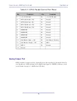
Page 60: ...input signal of 20dBFS and have a maxi mum balanced output of 24dBu into 600 ohms Pin Function Pin Function 1 5 V 150 mA 14 5 V 150 mA 2 GPI A Hold Low On 15 Ground 3 GPI B Hold Low On 16 Ground 4 GPI C Hold Low On 17 Ground 5 GPI D Hold Low On 18 Ground 6 RESERVED 19 Ground 7 RESERVED 20 Ground 8 RESERVED 21 Ground 9 RESERVED 22 Ground 10 Unit Status Open OK 23 Unit Status Common 11 Unit Status C...

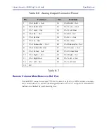
Page 61: ...rnal GPO indicators is limited by a self resetting fuse Pin Function Pin Function 1 Ch 8 Ro Rt Out 14 Ch 8 Ro Rt Out 2 Ch 8 Ro Rt Gnd 15 Ch 7 Lo Lt Out 3 Ch 7 Lo Lt Out 16 Ch 7 Lo Lt Gnd 4 Ch 6 Rs Out 17 Ch 6 RS Out 5 Ch 6 Rs Gnd 18 Ch 5 Ls Out 6 Ch 5 Ls Out 19 Ch 5 Ls Gnd 7 Ch 4 Subwoofer Out 20 Ch 4 Subwoofer Out 8 Ch 4 Subwoofer Gnd 21 Ch 3 Center Out 9 Ch 3 Center Out 22 Ch 3 Center Gnd 10 Ch ...

Page 62: ...vided to power an external micro phone or microphone preamplifier and is protected by self resetting fuses Table 8 9 Calibration Input Pin Connection 1 Mute GPI A 2 Return to Ref GPI B 3 GPO A High when Muted 4 GPO B High when at Ref 5 Ground 6 Encoder Phase A Input 7 NC 8 Encoder Phase B Input 9 5V 200 mA Max Pin Connection 1 NC 2 NC 3 Left Input 4 Ground Common 5 Ground Common 6 Right Input not ...

Reviews: