Linear Acoustic AERO.qc User Guide
Specifications
57
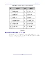
Table 8-6 Analog Output Connector Pinout
Table 8-7
Remote Volume/Mute/Return to Ref Port
Female DB-9 connector accepts TTL level controls, active Low. GPIs require a momen-
tary contact closure to activate their assigned function. The 5-V output for external GPO
indicators is limited by a self-resetting fuse.
Pin
Function
Pin
Function
1
Ch 8 Ro/Rt + Out
14
Ch 8 Ro/Rt - Out
2
Ch 8 Ro/Rt Gnd
15
Ch 7 Lo/Lt + Out
3
Ch 7 Lo/Lt - Out
16
Ch 7 Lo/Lt Gnd
4
Ch 6 Rs + Out
17
Ch 6 RS - Out
5
Ch 6 Rs Gnd
18
Ch 5 Ls + Out
6
Ch 5 Ls - Out
19
Ch 5 Ls Gnd
7
Ch 4 Sub Out
20
Ch 4 Subwoofer - Out
8
Ch 4 Subwoofer Gnd
21
Ch 3 Out
9
Ch 3 Center - Out
22
Ch 3 Center Gnd
10
Ch 2 Right + Out
23
Ch 2 Right - Out
11
Ch 2 Right Gnd
24
Ch 1 Left + Out
12
Ch 1 Left - Out
25
Ch 1 Left Gnd
13
NC
Summary of Contents for AERO.qc
Page 1: ...AERO qc Audio Quality Controller with Optional HD SD SDI and Dolby Decoding User Guide ...
Page 2: ......
Page 8: ...Linear Acoustic AERO qc User Guide viii ...
Page 12: ...Linear Acoustic AERO qc User Guide Introduction 8 ...
Page 22: ...Linear Acoustic AERO qc User Guide Applications 18 ...
Page 38: ...Linear Acoustic AERO qc User Guide Detailed Operation 34 This Page Blank or nearly so ...
Page 42: ...Linear Acoustic AERO qc User Guide Monitor Setup 38 ...
Page 46: ...Linear Acoustic AERO qc User Guide Troubleshooting 42 ...
Page 56: ...Linear Acoustic AERO qc User Guide Presets Processing Adjustment 52 NOTES ...


