2
dc1668abf
DEMO MANUAL DC1668A-B
PARAMETER
CONDITION
VALUE
Input Voltage Range
4.5V to 20V
Output Voltage V
OUT
Remove V
OUT
SEL Jumper for V
OUT
= 0.6V
DC
0.6V
DC
, 1V
DC
, 1.2V
DC
, 1.5V
DC
, 1.8V
DC
,
2.5V
DC
, 3.3V
DC
Maximum Continuous Output Current I
OUT(MAX)
Current Derating May Be Necessary for Certain V
IN
,
V
OUT
, Frequency and Thermal Conditions.
40A
DC
Default Operating Frequency
500kHz
External Clock Synchronous Frequency Range
250kHz to 770kHz
Output Voltage Ripple (Typical)
V
IN
= 12V, V
OUT
= 1.8V
500kHz (20MHz BW)
< 20mV
P-P
at I
OUT
= 40A, See Figure 5
Efficiency
V
IN
= 12V, V
OUT
= 1.8V
500kHz
87.3% at I
OUT
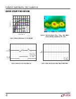
= 40A, See Figure 2
Load Transient
V
IN
= 12V, V
OUT
= 1.8V
See Figure 4
QUICK START PROCEDURE
PERFORMANCE SUMMARY
Demonstration circuit 1668A-B is easy to set up to evaluate
the performance of paralleled LTM4627 modules. Please
refer to Figure 1 for proper measurement equipment setup
and follow the procedure below:
1. With power off, connect the input power supply, load,
meters, and V
OUT
BNC cable as shown in Figure 1.
Preset the load to 0A and V
IN
supply to be 0V. Place
jumpers in the following positions for a typical 1.8V
OUT
application:
JP2
JP7
JP6
V
OUT
Select
RUN
TRACK/SS
1.8V
OFF
SOFT-START
2. Turn on the power at the input. Increase V
IN
to 12V
(Do not hot-plug the input supply or apply more than
the rated maximum voltage of 20V to the board or the
modules may be damaged).
3. Set the RUN pin jumper (JP7) to the ON position. The
output voltage should be regulated. The output voltage
meter should read 1.8V ±2% (1.76V to 1.84V).
4. Vary the input voltage from 5V to 20V and adjust the
load current from 0A to 40A. V
OUT
should remain
regulated at 1.8V ±2%. Observe the load regulation,
output voltage ripple, efficiency and other parameters.
Output voltage ripple should be measured at J6 with
a BNC cable and oscilloscope. The probe channel for
V
OUT
should be set at 50Ω termination resistance to
match the BNC Cable.
5. For optional load transient testing apply an adjustable
positive pulse signal between IOSTEP CLK and GND
pins. The pulse amplitude sets the load step current
amplitude. The pulse width should be short (< 1ms)
and pulse duty cycle should be low (< 15%) to limit the
thermal stress on the load transient circuit. The load
step current can be monitored with a BNC connected
to J5 (5mV/A).


