3
dc2261af
DEMO MANUAL DC2261A
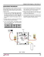
Quick start proceDure
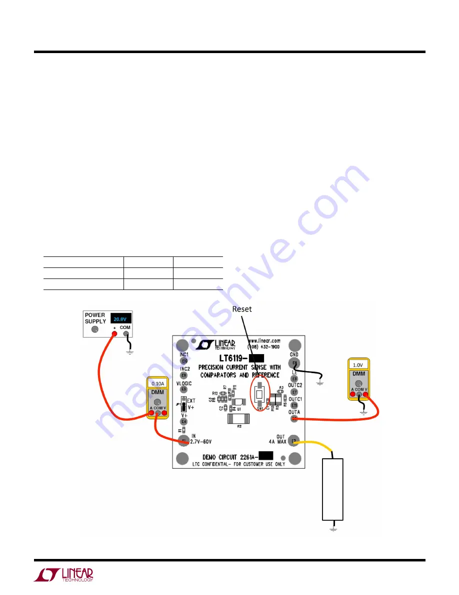
With the demonstration circuit, it is easy to set up and
evaluate the performance of the LT6119. Refer to Figure 1
for proper measurement equipment setup and follow the
procedure below:
1. With the power off, connect the power supply positive
to IN and the common to GND. With default settings
the supply can range from 2.7V to 60V. If the supply
does not have an accurate current readout, a DMM may
be connected in series with the supply as shown in
Figure 1.
2. Connect a voltmeter or oscilloscope to the OUTA with
the common input connected to ground.
3. Turn on the power supply. The comparator outputs
start in a known state as shown in the following table
if there is no load attached.
PART
OUTC1
OUTC2
DC2261A-A LT6119-1
High
Low
DC2261A-B LT6119-2
High
High
4. Connect a load to the demo board OUT terminal (posi-
tive) and ground. The load may be a power resistor,
active load instrument or a circuit of interest.
5. Measure the output voltage and confirm that it corre-
sponds to the load current. V
OUTA
(V
) = 10 •
I
LOAD
(A)
for the factory installed resistors.
6. If able, sweep load current from 0A to 300mA to verify
the operation of the comparators. Use the reset push
button to reset latched comparator outputs.
Figure 1. Test Setup
200Ω


