2
dc1575bfa
DEMO MANUAL DC1575B
Demonstration circuit 1575B is easy to set up to evaluate
the performance of the LTC4362. Refer to Figures 1 and 2
for proper measurement equipment setup and follow the
procedure below:
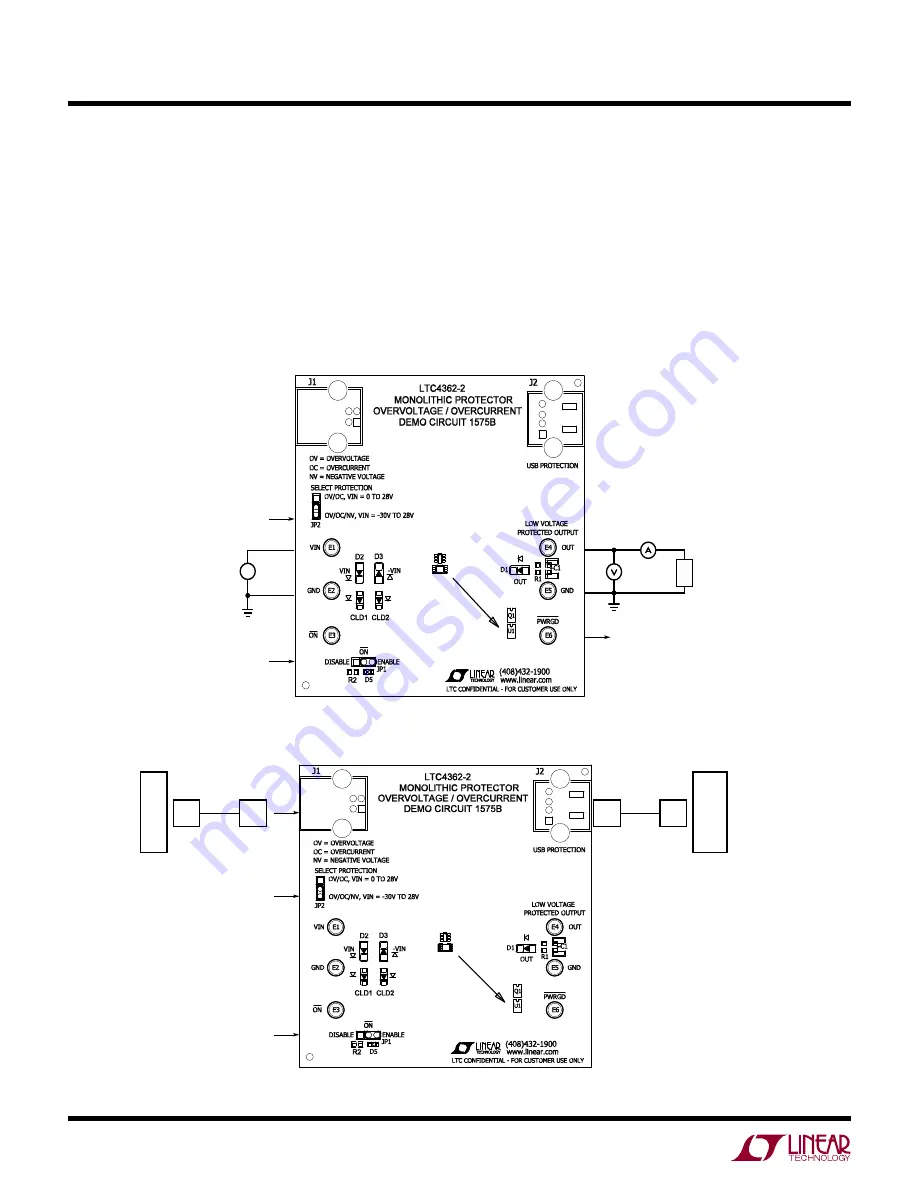
1) Connect the load and measurement across the OUT
and GND (Figure 1).
2) Select protection type at JP2:
a) For overvoltage and overcurrent protection select
OV/OC.
QUICK START PROCEDURE
b) For overvoltage, overcurrent and negative voltage
protection select OV/OC/NV.
3) Select ENABLE at JP1 to enable the protection.
4) Connect a power supply across V
IN
and GND.
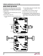
5) For USB protection, connect a USB cable from J2 to
the USB device (Figure 2). Select the protection type
at JP2. Connect a second USB cable from a computer
to J1.
Figure 1. DC1575B Basic Setup
Figure 2. DC1575B USB Protection Setup
SELECT PROTECTION
V
IN
SELECT ENABLE
+–
PROTECTED
OUT
PWRGD
LOAD
SELECT PROTECTION
USB
CABLE
(HOT PLUG)
SELECT ENABLE
USB
CABLE
PC
USB
DEVICE


