background image

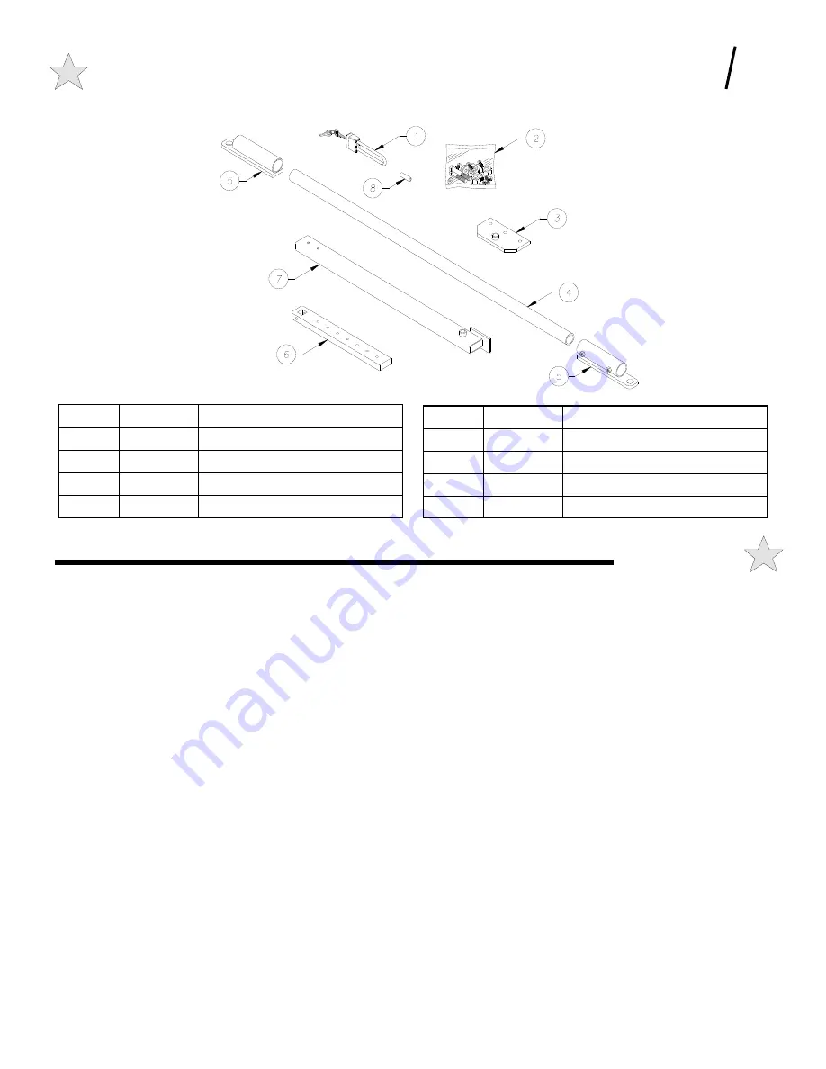
ITEM # 

 PART # 

DESCRIPTION 

104475 

TWIST'R ARM FITTING 

104875 

TWIST'R CRANK ARM 

104473 

TWIST'R CRANK ARM EXTENSION 

SPACER 

SPACER FOR PADLOCK (OPTIONAL) 

Figure 25:Gate Arm Kit 
Exploded View 

106360 

ITEM # 

 PART # 

DESCRIPTION 

010667 

PADLOCK WITH KEYS (OPTIONAL) 

102928 

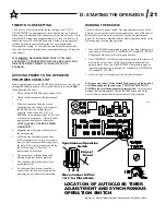
HARDWARE BAG, ARM KIT 

104476 

TWIST'R ARM BRACKET 

104448 

TWIST'R ARM 

NOTES 

 E

END USER INSTRUCTIONS 

GATE OPENER OPERATION & SAFETY GUIDE 


27 

Summary of Contents for Twist'R Plus SX4000

Page 1: ...lar Swing Gate Operator READ THIS MANUAL CAREFULLY BEFORE INSTALLATION OR USE SAVE THESE INSTRUCTIONS Serial Date Installed Your Dealer As of date of manufacture meets all ANSI UL 325 Safety Requirements for Vehicular gate operators Proven CGA2K TECHNOLOGY Twist R Plus ...

Page 2: ...d of DAMAGE to your gate gate operator or equipment Gives instructions to avoid the hazard Indicates an ELECTRICAL hazard of INJURY OR DEATH Gives instructions to avoid the hazard WARNING Indicates an ELECTRICAL hazard of DAMAGE to your gate gate operator or equipment Gives instructions to avoid the hazard CAUTION WA R N I N G H I G H V O LTA G E ONLY A QUALIFIED TECHNICIAN SHOULD SERVICE THIS GAT...

Page 3: ...c to eliminate hazards in your gate system design The torque limiting drive system also serves to protect the mechanical components of the operator The torque limiting drive setting is an adjustable setting that must be determined at the time of installation This setting must be tested periodically to ensure proper operation The more freely the gate will move the more sensitive the setting can be ...

Page 4: ... BE MINIMIZED BY INSTALLING A MESH SCREEN ON THE GATE Allstar strongly recommends the entire gate and adjacent fence area the gate covers when open be meshed or guarded such that a handhold or toehold cannot be achieved See Figure 2 The gate operator as described in this manual is a VEHICULAR GATE OPERATOR and as such is NOT INTENDED FOR PEDESTRIAN traffic In installations where pedestrian passage...

Page 5: ...IGHT IS NOT LIGHTED HIGH VOLTAGE AC MAY STILL BE PRESENT NEVER LEAVE THE INSTALLATION WITH THE CONTROL BOX COVER REMOVED ALWAYS TURN OFF THE POWER BEFORE ATTEMPTING SERVICE OF EITHER THE ELECTRICAL OR MECHANICAL SYSTEMS SECURELY ATTACH THE WARNING SIGNS provided with the RSX4000 on the gate one on the outside and one on the inside where they can be seen by persons in the area of the gate to alert ...

Page 6: ...potential of hitting the operator consideration should be given to installation of protective posts in front of the operator If a suitable concrete base already exists for mounting the operator it will be necessary to drill mounting holes for the RSX4000 operator 3 4 mounting holes are located on the front and rear of the optional pedestal The bolt pattern is shown in Figurez6 The mounting bolts s...

Page 7: ...ill be installed after the loop is positioned it is necessary to place the loops in Schedule 40 PVC pipe to maintain uniform loop spacing with respect to the surface of the pavement The loop should be placed 1 5 below the surface of the pavement and at least 2 above any reinforcing steel The lead in wires need not be in PVC but must have at least six 6 twists per running foot THE LOOP WIRES MUST B...

Page 8: ...15 Amp service is required for each operator unit The Nominal Distance column of Table 1 is the maximum recommended distance from the service breaker panel to the operator for a given wire size and voltage The values in the table are valid for one RSX4000 only The RSX4000 will operate at a voltage as low as 105 VAC as measured at the input terminals to the operator This should be checked as part o...

Page 9: ...t to drill mounting holes for concrete bolts 9 Multimeter to test line voltage and other measurements as necessary 10 Small level to level the RSX4000 operator at installation 11 Torque Wrench and 1 2 Socket 12 7 16 Socket or Wrench to remove cover bolts 13 9 16 Socket or Wrench for post or pedestal mounting bolts UNPACKING CHECKLIST The Twist R Plus as shipped consists of the components listed be...

Page 10: ...ced anchor bolts the procedure is the same except that the bolts will already be in place If 1 2 diameter anchor bolts were set the 3 4 mounting holes on the RSX4000 pedestal will allow some adjustment for desired alignment Washers can be used under low corners to accurately level the unit as above TO REVIEW Make sure the correct position of the pedestal or post from the center line of the gate hi...

Page 11: ...ECEIVER RECEIVER EMMITER 2 1 IN POWER POWER IN 4 NO NC 1 2 3 CLOSE PHOTELECTRIC 5 OPERATOR THRU BEAM THRU BEAM PHOTO Note 2 1 USE A UL RECOGNIZED COMPONENT THAT COMPLIES WITH CURRENT UL 325 REQUIREMENTS TERMINAL NUMBERS ABOVE REPRESENT MODEL IR55 WIRING FOR OTHERS SIMILAR 2 SELECT TERMINAL BASED ON FUNCTION DESIRED SEE TERMINAL STRIP REFERENCE CHART See Note 1 See Note 1 12 OPEN EDGE A B C D 11349...

Page 12: ... Note 1 2 SELECT TERMINAL BASED ON FUNCTION DESIRED SEE TERMINAL STRIP REFERENCE CHART TERMINAL NUMBERS ABOVE REPRESENT MODEL E3K WIRING FOR OTHERS SIMILAR 1 USE A UL RECOGNIZED COMPONENT THAT COMPLIES WITH CURRENT UL 325 REQUIREMENTS Note 2 PHOTO RETRO REFLECTIVE RETRO REFLECTIVE OPERATOR 5 CLOSE PHOTELECTRIC 3 2 1 NC NO 4 IN POWER REFLECTOR TRANSCEIVER TRANSCEIVER REFLECTOR 2 CLOSE 10 POWER IN 4...

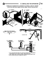
Page 13: ...7 OUTSIDE INSIDE OPENING ENTRAPMENT ZONE B OPEN EDGE SENSOR B A CLOSE EDGE SENSOR 113499 16 COMMON TERMINAL STRIP REVERSE 13 12 OPEN CLOSE 11 CLOSE EDGE OPERATOR EDGE EDGE Note 2 1 USE A UL RECOGNIZED COMPONENT THAT COMPLIES WITH CURRENT UL 325 REQUIREMENTS AN EDGE SENSOR THAT ACTIVATES ON THREE 3 SIDES SHOULD BE USED 2 SELECT TERMINAL BASED ON FUNCTION DESIRED SEE TERMINAL STRIP REFERENCE CHART S...

Page 14: ...so the crank arm will swing freely This is accomplished by loosening do not remove the two reducer slide clamp bolts on each side of the shaft support tower To prevent accidental damage to the limits etc the trigger pin should be removed at this time as shown in Figure 18 The tension on the flat poly v adjustable torque drive belt can now be relieved a small amount at a time until the large pulley...

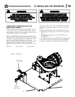
Page 15: ...e neutral green ground Connections for the 115 VAC service should be made according to the schematic wiring diagram Page 25 Service entry is shown in Figure 11 Starting at the RSX4000 power switch outlet proceed as follows 1 The BLACK wire attaches to the 115 VAC HOT wire normally black 2 The WHITE wire attaches to the 115 VAC NEUTRAL wire normally white 3 The GREEN wire attaches to the GROUND wir...

Page 16: ... see Figure 13 To change to a different handed operation the capacitor wires and limit wires must be changed For proper operation the limits and capacitor must be wired as shown SYNCHRONOUS OPERATION MASTER SLAVE Two RSX4000 units in a bi parting situation one wired right hand and one wired left hand see above can be configured to operate in a synchronous manner The units can be wired together to ...

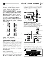
Page 17: ...al 2 24 VAC of the RSX4000 control panel FOUR WIRE RECEIVERS Four wire receivers replace the spade terminals on the RECEIVER with 4 wires These wires are typically color coded The instructions with the receiver must be carefully followed to properly connect the receiver For any 4 wire receiver two of the wires will be for power input and two will be for the relay contacts Connect the two wires for...

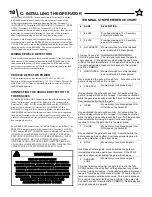
Page 18: ...ISK OF INJURY OR DEATH LOCATE KEYPAD CARD READER KEY SWITCH OR SIMILAR ENTRY DEVICES IN A LOCATION WHERE A USER CAN NOT REACH THROUGH THE GATE OR FENCE TO ACTIVATE THE GATE OPERATOR THE RECOMMENDED DISTANCE BETWEEN THE GATE OR FENCE AND ACCESSORY SWITCH IS 10 FEET NAME DESCRIPTION 1 24 VAC Provides maximum 10 VA auxiliary power for accessories 2 24 VAC Provides maximum 10 VA auxiliary power for ac...

Page 19: ...ut is active only when the gate is closing or when it s fully open and the Close Timer is operative All stand alone vehicle detectors photo eyes and active edges should be connected here and to terminals 3 or 13 COMMON Multiple devices may be connected in parallel 12 OPEN EDGE Momentary or continuous signal This input is active only when referenced to the opening direction it has no effect on the ...

Page 20: ... slipping action to occur between the flat Poly V belt and the large output pulley similar to that of a clutch mechanism Before turning the tensioning bolts it is necessary to loosen the four 4 reducer slide clamp bolts two each side of the shaft support tower and the motor mount clamp nut see Figure 9 Loosening the motor mount clamp nut allows the motor pulley to pivot Gravity will tension the V ...

Page 21: ...the procedures outlining the ATD on Page 17 Section C if readjustment is necessary 6 The proper Left or Right hand or Bi Parting wiring has been completed 7 The Limit Switch brackets have been preliminarily set 8 No other auxiliary devices should be connected to the terminal strip until the powering up procedures are completed RUNNING THE RSX4000 Turn ON the main power switch The gate should not m...

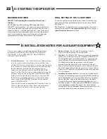
Page 22: ... panel of the detector and a metal plate over the loop When you are satisfied that the Detector is working properly connect the output wires to the REVERSING terminal on the control panel of the RSX4000 Give the gate an open command and allow the Timer to Close to start the gate to close Place the metal plate over the Loop and observe that the gate reopens 2 Shadow Loop See Section B regarding Veh...

Page 23: ...E The gate can be moved open or close in case of power failure or other need to move the gate manually from any position except fully closed without disconnecting the operator arm Remove power from the unit if not already off and firmly grasp the leading edge of the gate Push or pull the gate in the direction desired The amount of force required to move the gate will depend on the setting of the a...

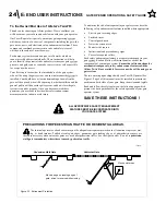
Page 24: ...ement features installed where appropriate Electric gate reversing edges Enclosed tracks Vertical guard posts Protective screen mesh Photoelectric sensors Instructional and precautionary signs Covers for exposed rollers Each safety enhancement feature is a separate component in your gate system Read and follow all instructions for each of the components of your unique system Ensure that all instru...

Page 25: ...e a qualified service technician make repairs to the gate MAINTAIN ALL COMPONENTS OF GATE SYSTEM Follow the maintenance instructions included with the gate the gate operator and the safety enhancement features and or accessories that make up your gate operator system Have a professional service technician perform any adjustments or maintenance to the components Fully test all safety enhancement fe...

Page 26: ...E END USER INSTRUCTIONS GATE OPENER OPERATION SAFETY GUIDE 26 Wiring Diagram 111811 ...

Page 27: ... ARM EXTENSION 8 SPACER SPACER FOR PADLOCK OPTIONAL Figure 25 Gate Arm Kit Exploded View 106360 ITEM PART DESCRIPTION 1 010667 PADLOCK WITH KEYS OPTIONAL 2 102928 HARDWARE BAG ARM KIT 3 104476 TWIST R ARM BRACKET 4 104448 TWIST R ARM NOTES E END USER INSTRUCTIONS GATE OPENER OPERATION SAFETY GUIDE 27 ...

Page 28: ... accepted In no event will Linear be responsible for goods returned without proper authorization or identification Goods returned to Linear for warranty repair within the warranty period which upon receipt by Linear are confirmed to be defective and covered by this limited warranty will be repaired or replaced at Linear s sole option at no cost and returned pre paid Defective parts will be repaire...

Reviews: