background image

VS-GSWG  Swing Gate Operator Installation Guide 

- 5 -


P1250 Revision X6 7-8-2011

Operator Setup

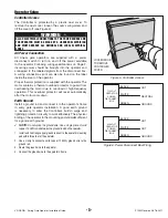
Controller Access

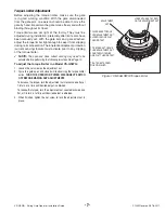
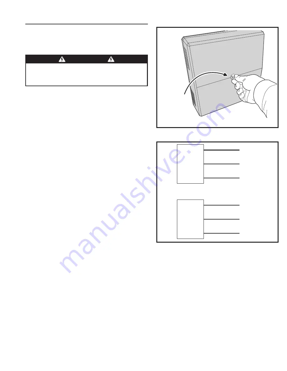
The Controller is protected by a plastic dust cover. To 
remove the dust cover, loosen the cover’s wing-screw and 
lift the cover off (see Figure 5).

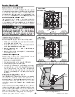
AC Power Connection

All Linear gate operators are supplied with a power 
disconnect switch to turn on and off the power available 
to the operator. Following wiring specifi cations on Page 2, 
incoming power should be brought into the operator and 
connected to the labeled pigtails from the disconnect box. 
A wiring connections print can also be found on the label 
inside the cover of the operator.

Proper thermal protection is supplied with the operator. The 
motor contains a thermal overload protector to guard from 
overheating the motor due to overload or high-frequency 
operation. This overload protector will reset automatically 
after the motor cools down.

Earth Ground

Install a ground rod and connect it to the operator’s frame 
in every gate operator installation. A good earth ground 
is necessary to allow the Controller’s built-in surge and 
lightning protection circuitry to work effectively. The physical 
bolting of the operator to the mounting posts 

is not

 suffi cient 

for a good earth ground.


NOTE:

 Do not splice the ground wire. Use a single piece of solid 

copper 12 AWG wire between the ground rod and the operator.

1.  Install an 8-foot long copper ground rod next to the operator mounting 

pad within three feet of the operator.

2.  Use a clamp to connect a solid copper 12 AWG ground wire to the 

ground rod.

3.  Route the ground wire to the operator.

4.  Connect the ground wire to the operator’s frame.

Figure 5. Controller Access

Figure 6. Power Disconnect Box Wiring

LOO

S

EN KNO

B

TO 

R

EMOVE

CONT

R

OLLE

R

COVE

R

110 VOLT

OPERATOR

POWER

DISCONNECT

BOX

BLACK

220 VOLT

OPERATOR

POWER

DISCONNECT

BOX

WHITE

GREEN

BLACK

WHITE

GREEN

HOT

NEUTRAL

GROUND

HOT

HOT

GROUND

 WARNING 

ALL AC ELECTRICAL CONNECTIONS TO THE POWER SOURCE AND 
THE OPERATOR MUST BE MADE BY A LICENSED ELECTRICIAN 
AND MUST OBSERVE ALL NATIONAL AND LOCAL ELECTRICAL 
CODES

Summary of Contents for VS-GSWG

Page 1: ... Installation Guide USA Canada 800 421 1587 800 392 0123 760 438 7000 Toll Free FAX 800 468 1340 www linearcorp com Operator models contained in this manual conform to UL325 standard for use in Class I II III and IV applications ...

Page 2: ...rn 17 Radio Transmitter Delete 17 MGT Obstacle Transmitter Learn 17 MGT Obstacle Transmitter Delete 17 Motor Type Selection 17 Reset Controller to Factory Defaults 17 Loop Layout Illustration 18 Safety Edge Layout Illustration 19 Photoeye Installation Illustration 20 Dual Gate Installations 21 Optional In Cabinet Heater 21 Gate Operation 22 Open Button 22 Close Button 22 Stop Button 22 Single Inpu...

Page 3: ...ces The following contact or non contact obstruction detection devices have been approved for use with this swing gate operator as part of a UL325 compliant installation Contact Edges Miller Edge Models MGO20 MGR20 MGS20 ME120 Photoeyes MMTC Model IR 55 165 range P N 2520 441 MMTC Model E3K 28 range P N 2520 031 Safety Information and Warnings Regulatory Warnings Read the following before beginnin...

Page 4: ...er may cause interference and faulty signals in some accessories 3 A three wire shielded conductor cable is required to connect two operators together for dual operation You must use Belden 8760 Twisted Pair Shielded Cable or equivalent only P N 2500 1982 per foot See Page 21 for details of this connection Note The shield wire should be connected in both the operators WARNING ALL AC ELECTRICAL CON...

Page 5: ...side top and bottom two 3 16 side plates go on the inside top and two 1 2 side plates go on the inside bottom see the illustration at right The operator should be positioned at a level to allow the arm to be installed at mid height on the gate H dimension can vary depending on gate construction Make sure the posts do not protrude above the operator cabinet NOTE If non standard mounting is necessar...

Page 6: ...or right hand installations Gate Arm Assembly Refer to Figure 4 1 Remove the arm assembly cover 2 Place the center hole in the rail guide over the 1 drive shaft 3 Place the drive sprocket on drive shaft Be sure the keyway is in place and set screws are secured 4 Connect the gate bracket to the gate Manually open the gate to approximately half open position 5 String the arm assembly chain as shown ...

Page 7: ...d rod and connect it to the operator s frame in every gate operator installation A good earth ground is necessary to allow the Controller s built in surge and lightning protection circuitry to work effectively The physical bolting of the operator to the mounting posts is not sufficient for a good earth ground NOTE Do not splice the ground wire Use a single piece of solid copper 12 AWG wire between...

Page 8: ... can be made by adjusting a few teeth on the nut at a time If the gate stops during travel you may need to adjust the Open or Close Current Setting or the Maximum Run Timer see Pages 13 14 Setting Speeds using LSO 2 LSC 2 Limit switches LSO 2 and LSC 2 control when the operator accelerates to maximum speed and decelerates to minimum speed It is recommended that LSO 2 and LSC 2 are adjusted first s...

Page 9: ...and close current sensing may need to be adjusted before performing the following two steps See Page 13 To adjust the torque limiter in a Model VS GSWG 1 Loosen the set screw on the adjustment nut 2 Cycle the gate open and closed while observing the torque limiter action TURN THE OPERATOR POWER DISCONNECT SWITCH OFF BEFORE MAKING ANY ADJUSTMENTS To increase the torque turn the adjustment nut clock...

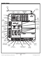
Page 10: ...BUTTON TERMINALS SOLAR PANEL TERMINALS BATTERY TERMINALS PLUG IN LOOP DETECTOR CONNECTORS PRIMARY SECONDARY COMM LINK TERMINALS SINGLE INPUT TERMINALS FIRE DEPT INPUT TERMINALS OPEN INPUT TERMINALS 3 BUTTON STATION TERMINALS OPEN AND CLOSE OBSTRUCTION INPUT TERMINALS REVERSE INPUT TERMINALS OPEN LOOP INPUT TERMINALS REVERSE LOOP INPUT TERMINALS SHADOW RESET LOOP INPUT TERMINALS LIMIT SWITCH INPUT ...

Page 11: ...AND OPERATION OPEN LIMIT BRAKE DELAY OPEN LIMIT SWITCH IS ACTIVATED CLOSE CURRENT SET MOTOR CURRENT HAS EXCEEDED THE CLOSE CURRENT SETTING WHILE CLOSING SET MAXIMUM CLOSE CURRENT CLOSE OBSTR MGT 1 SET CLOSE OBSTRUCTION TERMINAL CONNECTED TO COMMON BY BEAM OR SAFETY EDGE OR SIGNAL FROM MGT OBSTACLE TRANSMITTER SET MGT 1 FUNCTION CLOSE RELAY AUTO CLOSE SET CLOSE RELAY IS ACTIVATED SET AUTO CLOSE TIM...

Page 12: ... OCCUR AGAIN PRIOR TO REACHING A LIMIT THE GATE WILL STOP AGAIN LOCKOUT AND SOUND THE CONTINUOUS TONE ALARM O OBS C OBS CLOSE OBSTRUCTION INPUT CONNECT TO NORMALLY OPEN DEVICES GATE EDGE PHOTO BEAM TO DETECT AN OBSTRUCTION DURING CLOSING WHILE GATE IS MOVING ANY CLOSE OBSTRUCTION SIGNAL WILL CAUSE THE GATE TO STOP THEN REVERSE AND TRAVEL TO THE FULL OPEN POSITION SHOULD A OPEN OBSTRUCTION INPUT OR...

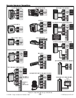
Page 13: ...E CHANNEL RADIO RECEIVER WIRELESS GATE EDGE SENSOR MGT TRANSMITTER PHOTOEYE FOR REVERSE PHOTOEYE FOR OPEN OBSTRUCTION TELEPHONE ENTRY KEYPAD EXTERNAL POWER SOLENOID LOCK MAGLOCK WARNING STROBE OR AUDIBLE SOUNDER GATE EDGE SENSOR FOR REVERSE CHANNEL 1 OPEN CLOSE TWO CHANNEL RADIO RECEIVER PHOTOEYE FOR CLOSE OBSTRUCTION Figure 12 Operator Accessory Connections ...

Page 14: ...of the driveway when viewed from the inside of the gate For left hand installations program the Controller for left hand operation Dual Gate Enable The factory default is for single gate operation For dual gate operation wire the two gate controllers together through the COMM LINK terminals see Page 21 and enable dual gate operation with this programming step NOTE The Mid travel Stop feature is di...

Page 15: ...nt load exceeds the programmed maximum load range number the operator will stop reverse and travel to the full open position Should a open obstruction input or an open direction inherent entrapment condition occur prior to the gate reaching the open limit the operator will lockout and sound the continuous tone alarm Another close request will be required to start the operator again If after restar...

Page 16: ...e Stagger Mode to OFF In dual gate installations the two operators communicate through the 3 wire COMM LINK interface When using the Stagger Mode set one operator for delayed opening and the other operator for delayed closing The Stagger Time programming function see below sets the length of the delay NOTE This function will only be displayed if dual gate operation is selected Stagger Delay Time T...

Page 17: ...s Constant Pressure Mode The factory default allows momentary pressure on a control station s OPEN or CLOSE button to cycle the operator The controller can be set to require constant pressure on the OPEN CLOSE or both buttons to run the operator NOTE If a button is set for constant pressure and it is released before the operator reaches the open or close limit the operator will stop the gate at it...

Page 18: ...r the shadow loop has been triggered by the vehicle and then has cleared after the vehicle passes the Auto Close Timer or a CLOSE command is required to begin closing the gate If the Anti tailgate Enable is set to ON the gate will close immediately as soon as the shadow loop has cleared Any subsequent shadow loop triggers while the gate is closing will stop the gate When the shadow loop clears the...

Page 19: ...ON TO DELETE ALL MGT TRANSMITTERS PRESS ENTER FOR 2 SECONDS TO EXIT WITHOUT DELETING ANY QUICKLY PRESS ENTER ERASE MGT TRANSMITTERS MD WILL BLINK FOR 30 SECONDS WHILE THE CONTROLLER IS READY TO DELETE ALL MGT TRANSMITTERS MD ENTER PRESS ENTER ENTER THE DISPLAY WILL SHOW DELETE ALL AND THE CONTROLLER RETURNS TO PROGRAMMING MODE FUNCTION TO DELETE ALL TRANSMITTERS PRESS ENTER FOR 2 SECONDS OR TO PIC...

Page 20: ...VS GSWG Swing Gate Operator Installation Guide 18 P1250 Revision X6 7 8 2011 Loop Layout Illustration ...

Page 21: ...s shall be located on the bottom edge A hardwired contact sensor shall be located and its wiring arranged so that the communication between the sensor and the gate operator is not subjected to mechanical damage A wireless contact sensor such as one that transmits radio frequency RF signals to the gate operator for entrapment protection functions shall be located where the transmission of the signa...

Page 22: ...VS GSWG Swing Gate Operator Installation Guide 20 P1250 Revision X6 7 8 2011 Photoeye Installation Illustration ...

Page 23: ...s Setthefollowingparametersineachgateoperatorindividuallyinasinglegate mode before connecting the network cable and operating in dual gate mode 1 Open and Close Limit settings 2 Open and Closed direction inherent entrapment protection OC CC After these parameters have been set and each operator has been tested independently and is functioning correctly in single gate mode then set BOTH operators t...

Page 24: ... will lockout and sound the continuous tone alarm Another close request will be required to start the operator again If after restart the overload or a close obstacle happens again before the close limit is reached the operator will lockout and sound the alarm If the auto close timer is set when the close obstruction input is cleared the gate will close when the auto close timer expires Reverse In...

Page 25: ...aximum Run Time has been exceeded the sounder will beep twice every five seconds The next operation of the gate will clear the indication CONTROLLER ERROR CAUSES AND INDICATIONS ERROR CAUSE ERROR INDICATION HOW TO CLEAR TWO SAFETY REVERSALS ON SINGLE GATE OR ON EITHER DUAL GATE En 00 CONTINUOUS ALARM BEEPER GATE DISABLED PRESS STOP BUTTON MAXIMUM RUN TIMER EXCEEDED ON OPENING En 01 AND MAX RUN LED...

Page 26: ...ore adjusting the current sensing B The Maximum Run Timer may have counted down and expired This can be caused by having the timer set too low if a chain or belt is broken or if a sprocket or pulley is slipping When the timer expires the gate stops and the beeper will sound C An obstruction signal from an accessory wired to the obstruction input may have triggered falsely Check the control board f...

Page 27: ...witches and limit actuators cams limit nuts etc for wear and replace as required In rotary limit switch assemblies wipe the limit shaft clean and apply a light coating of dry lubricant 5 For operators with magnetic brakes check for proper adjustment Brake disc must run free when the brake is engaged For brake assemblies other than C face style the brake should be adjusted so that the solenoid plun...

Page 28: ...VS GSWG Swing Gate Operator Installation Guide 26 P1250 Revision X6 7 8 2011 Model VS GSWG Exploded View ...

Page 29: ...PLT Moisture Seal Spacer 2 14 2200 016 Moisture Seal 15 2400 067 Seal Washer 1 x 2 1 2 18 2200 097 Gear Reducer 60 1 19 2200 968 Sprocket 40 B 22 1 bore 20 2100 735 Limit Box Mounting Plate 21 2520 453 Rotary Limit Box Assembly 22 2200 008 Sprocket 48 B 10 1 2 bore 23 2200 459 40 Roller Chain 27 1 2 Links 24 2200 006 40 Master Link 25 2200 200 48 Roller Chain 27 Links 26 2200 010 48 Master Link 27...

Page 30: ...er 2520 552 2 HP 208 230V 3 Phase Controller 2520 553 2 HP 460V 3 Phase Controller 1 2120 447 Enclosure with Cover Transformers 2 2500 212 115V to 24V 40VA 2500 791 208 230V to 24V 40VA 2500 214 460V to 24V 40VA REF PART DESCRIPTION Hitachi Controllers 3 2500 2244 1 2 HP 115V 1 Phase 2500 2246 1 2 HP 208 230V 1 Phase or 3 Phase 2500 2249 1 2 HP 460V 3 Phase 2500 2245 1 HP 115V 1 Phase 2500 2247 1 ...

Page 31: ...ld be necessary for normal operation PLEASE CONSULT THE FACTORY BEFORE MAKING ANY CHANGES List of parameters set at factory MODEL L100 MODEL L200 FUNCTION DESCRIPTION RECOMMENDED SETTING FUNCTION DESCRIPTION RECOMMENDED SETTING F02 ACCEL TIME 3 0 F002 ACCEL TIME 3 00 F03 DECEL TIME 3 0 F003 DECEL TIME 3 00 A01 SPEED SOURCE 00 POT A001 SPEED SOURCE 00 POT A02 RUN COMMAND SOURCE 01 A002 RUN COMMAND ...

Page 32: ...4 2400 026 Spring Pin 3 16 x 1 15 2100 051 Lower Rail Guide 16 2100 052 Rain Cover 19 2400 004 Key 1 4 x 1 4 x 1 22 2100 054 Chain Tension Bolt 23 2400 015 Hex Nut 3 8 16 24 2200 006 40 Master Link 25 2200 658 40 Chain 72 Links 26 2100 1168 BT Cover for 78 Arm Parts for non standard 63 VS GSWG Gate Arm 2110 257 Gate Arm Assembly 63 complete 1 2110 271 Welded Rail Assembly 63 25 2200 420 40 Chain 5...

Page 33: ...VS GSWG Swing Gate Operator Installation Guide 31 P1250 Revision X6 7 8 2011 This page left blank intentionally ...

Page 34: ...s and reverses a short distance with minimal resistance applied 40 lbs on a swing gate at the end of the gate 75 lbs on a slide gate 8 The installer has instructed the customer in the proper use of the gate operator and reviewed all of the operational functions obstruction sensing devices warning beeper and reset etc 9 The installer has instructed the customer in the proper use of the operator s m...

Reviews: