-5-
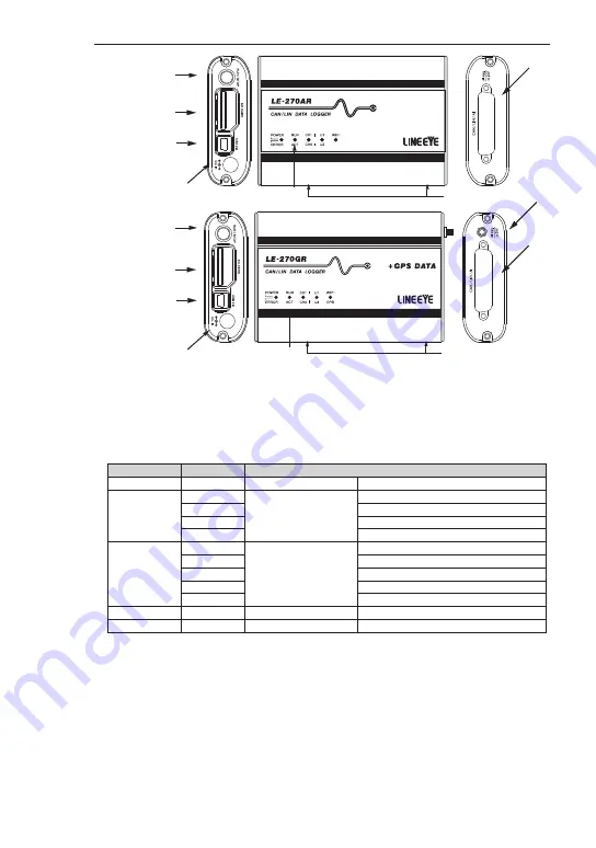
1.3 Explanation of Each Part
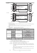
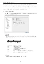
1) Measurement Interface
The measurement interface consists of a DSUB 25pin connector to connect to CAN/LIN target devices
and external input signals.
Measurement port is isolated from USB port by galvanic isolation(1kV) (Only LE-270GR).
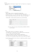
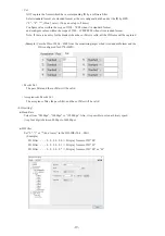
2) LED
POWER/ERROR : Indicate the operating status of analyzer.
RUN/ACT : Indicate that analyzer is measuring or accessing to the SD card.
1)
3)
4)
2)
5)
6)
7)
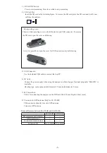
*1: Do not remove the SD card while lighting.
*2: Contact LINEEYE distributors or LINEEYE for support.
CH1/CH2 : It displays the logic status of CH1 line (green) and CH2 line (red).
U1/U2 : Able to light the U1 (green) /U2 (red) by trigger actions.
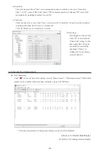
WiFi/GPS : When you select “Station” in the Wi-Fi setting of “Wireless LAN configuration file”,
the LED lights in green (Wi-Fi) when it completes connecting with an external Wi-Fi
access point.
When you select “Access point” in the Wi-Fi setting, it lights in green (Wi-Fi) when
the access point in the analyzer runs.
For LE-270GR only, the LED lights in red (GPS) when the analyzer receives a GPS
radio.
Note : The LED is two colors LED and it looks orange when both of them light.
POWER/ERROR RUN/ACT
Status
Light off
Light off
Power Off
Green light
Light off
Protocol Analyzer Mode
Ready to operate
Green light
Measuring
Red light
Accessing to the SD card
*1
Orange light
Measuring and Accessing to the SD card
*1
Orange light
Light off
Logger Mode
Ready to operate
Green light
Measuring
Green blinking
Ready to start measuring
Red light
Accessing to the SD card
*1
Orange light
Measuring and Accessing to the SD card
*1
Light off
Green light
Firmware Update Mode
Red blinking
-
Error
Self-check error, Unusual error
*2
8)
3)
4)
2)
5)
6)
7)
1)
LE-270AR
LE-270GR
A
N
T.


