ALIMENTAZIONE/
POWER SUPPLY
MASSIMA POTENZA ASSORBITA/
MAX POWER ABSORPTION
GRADO DI PROTEZIONE/
PROTECTION DEGREE
CLASSE DI ISOLAMENTO/
INSULATING CLASS
SEZIONE DEL CAVO/
WIRE DIAMETER
CARATTERISTICHE TECNICHE/
TECHNICAL CHARACTERISTICS
230Vac - 50Hz
6VA
IP 40-IP65
II
0,5 ÷ 5mm
2
APPARECCHIO DI EMERGENZA
EMERGENCY LUMINAIRE
CRISTAL
ENERGY TEST - SPY SYSTEM
IP40-IP65
ISTRUZIONI PER L'INSTALLAZIONE E L'USO
INSTALLATION AND USE INSTRUCTIONS
I
UK
Attenzione: In caso di installazione a parete il prodotto deve essere disposto
con i led verso il BASSO
BATTERIE:
Sostituire la batteria ogni quattro anni o quando l'autonomia non è più quella
nominale. C'è uno spazio da riempire a cura dell'installatore con la data di
entrata in funzione.
Attenzione: Le batterie al Ni-Cd e Ni-MH sono inizialmente scariche, la
prima ricarica deve durare almeno 48h.
Warning: In case of wall mounting the product must be positioned with the leds
down.
BATTERIES:
It is recommended to substitute each battery every four years or when the nominal
autonomy is not guaranteed. There is a place where the installer can write the
date of the first starting
Warning: The Ni-Cd and Ni-MH batteries are sold uncharged: the first charge
must be 48h long.
GENERAL CHARACTERISTICS:
- Indicator green Led for the presence of the power supply.
- Indicatore red Led for the warnings signallings.
- Operation with rechargeable Ni-Cd and NiMH batteries.
- Constant current electronic device for the charge of the battery.
- Electrical protection device for the excessive discharge of battery.
- Possibility to be put in the stand-by mode by remote control Commander
(optional)
- Possibility to put a green signal label .
- Plastic body in accordance with the rules in force.
CARATTERISTICHE GENERALI:
- Led spia verde per presenza rete.
- Led spia rosso per segnalazione anomalie.
- Funzionamento con batterie ricaricabili al Ni-Cd e al NiMH.
- Dispositivo di ricarica delle batterie a corrente costante.
- Dispositivo di protezione contro la scarica eccessiva della batteria.
- Possibilità di messa in stato di riposo tramite il comando remoto Commander
(opzionale).
- Possibilità di applicare dei pittogrammi di segnalazione.
- Corpo in materiale plastico conforme alle normative vigenti.
EN 60598-1 EN 60598-2-22
2002/95/CE
RoHS
Compliant
MADE IN ITALY
230 Vac - 50 Hz
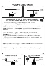
FUNZIONI DI TEST:
- La lampada esegue due tipi di test temporizzati: il test funzionale e il test di
autonomia. I test funzionale e di autonomia possono essere effettuati anche
manualmente con il Commander quando la batteria è in ricarica di
mantenimento.
- Tutti i test manuali vengono eseguiti se ci sono le condizioni ambientali
idonee di luce esterna. Se le condizioni esterne non sono idonee il test viene
rinviato al primo verificarsi delle condizioni idonee. Durante il tempo di attesa il
led verde lampeggia per segnalare che la lampada sta aspettando di potere
compiere i test.
Test funzionale:
viene effettuato ogni 15 giorni e consiste nella accensione
della lampada fluorescente per una durata di 5-20 secondi. Per attivare il test
funzionale manuale premere una volta il Commander ON (effettuare una
pressione breve della durata non superiore a 2 secondi)
Test di autonomia:
viene effettuato ogni 84 giorni e consiste nella completa
scarica della batteria. P
e il test di autonomia premere una volta il
er far partir
Commander ON (effettuare una pressione lunga della durata non inferiore a 5
secondi).
Disabilitazione dei test:
tutti i test temporizzati possono essere inibiti tramite
la pressione di un tasto del Commander OFF, ad una seconda pressione del
tasto ON i test temporizzati verranno riabilitati.
TEST FUNCTIONS:
-The lamp makes two kinds of deliberate time tests: the functional test and the
duration test. The functional test and the duration test can be made also in the
manual way with the use of the Commander in the normal charge mode.
-All the manual tests can be made only if there is the good ambient condition of
external light. If the external conditions aren't good the test is postponed to the
first coming of the good conditions. In the time of waiting the green led flashes
to indicate that the lamp is waiting for the test.
The functional test:
is done every 15 days and consists in the lighting of the
fluorescent lamp for a duration of 5-20 seconds. To start the manual functional
test push one time the Commander ON (make a short push no more than 2
seconds)
The duration test:
is done every 84 days and consists in the complete
discharge of the battery. To start the duration test push one time the
Commander ON (make a long push no less than 5 seconds).
Disabilitation of the tests:
all deliberate time tests can be disabled with a
pushing of the button of Commander OFF, with a second pushing of the
Commander ON deliberate time tests will be enabled.
INSTALLAZIONE: (FIG.2)
-Rimuovere il diffusore trasparente
1
facendo leva con
dei cacciaviti nei punti
2
.
-Sganciare il riflettore
3
dalla base
4
facendo leva con un cacciavite nel punto
5
.
-Forare se necessario uno dei tre possibili ingressi laterali per il cavo di
alimentazione ed applicare
la base
4
al muro tramite gli appositi fori per il fissaggio.
-Eseguire i cablaggi come esposto in fig.3,4,5,6
-Riagganciare il riflettore
3
alla base
4
facendo scattare il denti nel punto
5
.
-Riagganciare il diffusore trasparente
1
alla base
4
facendo scattare i denti nei
punti
2
.
INSTALLATION: (FIG.2)
-Remove the transparent cover
1
pushing with a screwdriver
in the points
2
.
-Unhook the body of the lamp
3
from the base
4
with a screwdriver in the point
5
.
-Drill in necessary one of the three possible entries for the power supply cable
and fix the base
4
to the wall using the holes on the base.
-Make the connections as shown on fig.3,4,5,6.
-Hook the body
3
to the base
4
making release the tooth on point
5
.
-Hook the transparent cover
1
to the base
4
making release the tooth on points
2
.
N.B.
inserire i tappi in dotazione negli appositi spazi laddove
viene inserito il tassello per l’installazione, al fine di per
garantire la tenuta stagna dell’apparecchio.
N.B.
In order to ensure the watertight integrity
of the fitting insert the covers coming with the product
in the reserved places where the screws anchors are
inserted.
INSERIRE IL RACCORDO
IN DOTAZIONE PER GARANTIRE
LA TENUTA STAGNA.
INSERT THE IP65 CONNECTOR
SUPPLIED TO ENSURE THE WATER-
TIGHT INTEGRITY OF THE FITTING.
5
5
4
3
2
2
2
2
1
Fig.2
Fig.2b
03


