CHAPTER 2 MAINTENANCE
M750L SERVICE MANUA 18.0
CHAPTER 2 MAINTENANCE PAGE. 2- 9
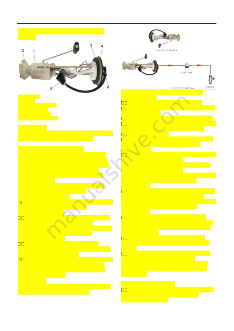
Appearance & Components of Fuel
Module
1. Fuel Pump
2. Strainer
3. Gasket, Fuel Module
4. Module Bracket
5. Module Harness
6. Fuel Tube (out pump)
Dimensions
Fuel Module Cover in elliptical shape with outer
edge dimensions as 115mm x 65mm.
Identification and Markings
Fuel Module, Fuel Pump and Regulator are
marked with batch code in Julian Date Code.
On Fuel Module, batch code in mentioned on
the label available on fuel module cover.
On Fuel Pump Batch code is engraved on
pump body (shell).
On Fuel Pressure Regulator, batch code is
engraved on regulator dome area.
Operating Conditions
Fuel Pump Module needs to be mounted on
Fuel Tank Bottom according to the
installation instructions.
Fuel Pump Module is intended to use with
gasoline. However if the fuel contains
ethanol, please contact vehicle manufacture to
check whether the fuel pump module
itself can survive or not.
Make sure there is at least 3 liters of
gasoline in the fuel tank before priming for first
time (do not run the pump dry)
Fuel Hose connections needs to be installed
according to the fuel flow diagram shown
Fuel Flow Description in vehicle fuel system
Service Procedure
Precautions:
Before attempting any service on fuel system,
following cautions should be always
followed for personal safety and to avoid
system damages.
Disconnect negative cable at battery.
DO NOT smoke, and place ‘No SMOKING”
sign near work area
Make sure to have fire extinguisher handy.
Make sure to perform work in well ventilated
area and away from any open fire/flames.
Wear Safety glasses
To relieve fuel vapor pressure in fuel tank,
remove fuel filler cap fuel filler neck and
then reinstall it.
As fuel lines are at high pressures when the
engine is stopped, loosening or
disconnecting fuel line will cause dangerous
spout of fuel. Before loosening/
disconnecting fuel lines, please follow the “Fuel
Pressure Relief Procedure” described
in this section.
Small amount of fuel may drip after the fuel
lines are disconnected. In order to reduce
the risk of personal injury, cover the pipe/ hose
ends with suitable blind with no rust or
contamination.
After servicing, make sure that the fuel
hoses and clamps are connected according to
the hose fitment instructions given in vehicle
instruction manual.
After servicing, please follow the ‘Fuel
Leakage Check Procedure’ described in this
section.
After servicing make sure to fill at least 3
liters gasoline before pump is primed
(ignition key should be turned on only after
ensuring there is minimum 3 liters of fuel in
the fuel tank)
Fuel Module Removal:
Relieve fuel pressure in fuel lines referring
to the ‘Fuel Pressure Relief Procedure’
provided in this section.
Summary of Contents for HY740STL 2018
Page 2: ...M750L ATV SERVICE MANUAL 18 0 M750L 18 0...
Page 11: ...CHAPTER 1 GENERALINFORMATION M750L SERVICE MANUAL 18 0 CHAPTER 1 GENERAL PAGE 1 6...
Page 13: ...CHAPTER 1 GENERALINFORMATION M750L SERVICE MANUAL 18 0 CHAPTER 1 GENERAL PAGE 1 8 NOTES...
Page 31: ...CHAPTER 2 MAINTENANCE M750L SERVICE MANUA 18 0 CHAPTER 2 MAINTENANCE PAGE 2 18 NOTES...
Page 93: ...CHAPTER 3 ENGINE M750L SERVICE MANUAL 18 0 CHAPTER 3 ENGINE PAGE 3 62 3 13SHIFT SYSTEM...
Page 144: ...CHAPTER 4A CHASSIS M750L SERVICE MANUAL 18 0 CHAPTER 4 CHASSIS PAGE 4 6 NOTES...
Page 168: ...CHAPTER 5 FINAL DRIVE LH500ATV D SERVICE MANUAL 14 0 CHAPTER 5 FINAL DRIVE 5 24 NOTES...
Page 182: ...CHAPTER 6 BRAKES M750L SERVICE MANUAL 18 0 CHAPTER 6 BRAKES PAGE 6 14 NOTES...
Page 184: ...CHAPTER 7 ELECTRICAL M750L SERVICE MANUAL 18 0 CHAPTER 10 ELECTRICAL 10 2...
Page 189: ...CHAPTER 7 ELECTRICAL M750L SERVICE MANUAL 18 0 CHAPTER 10 ELECTRICAL 10 7 LH700ATV EFI MODEL...
Page 209: ...CHAPTER 8 ELECTRICAL M550 SERVICE MANUAL 16 0 CHAPTER 7 ELECTRICAL CTRICAL PAGE 8 27...


