April 17, 2000
Man ual Versio n 1.0
4.2
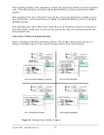
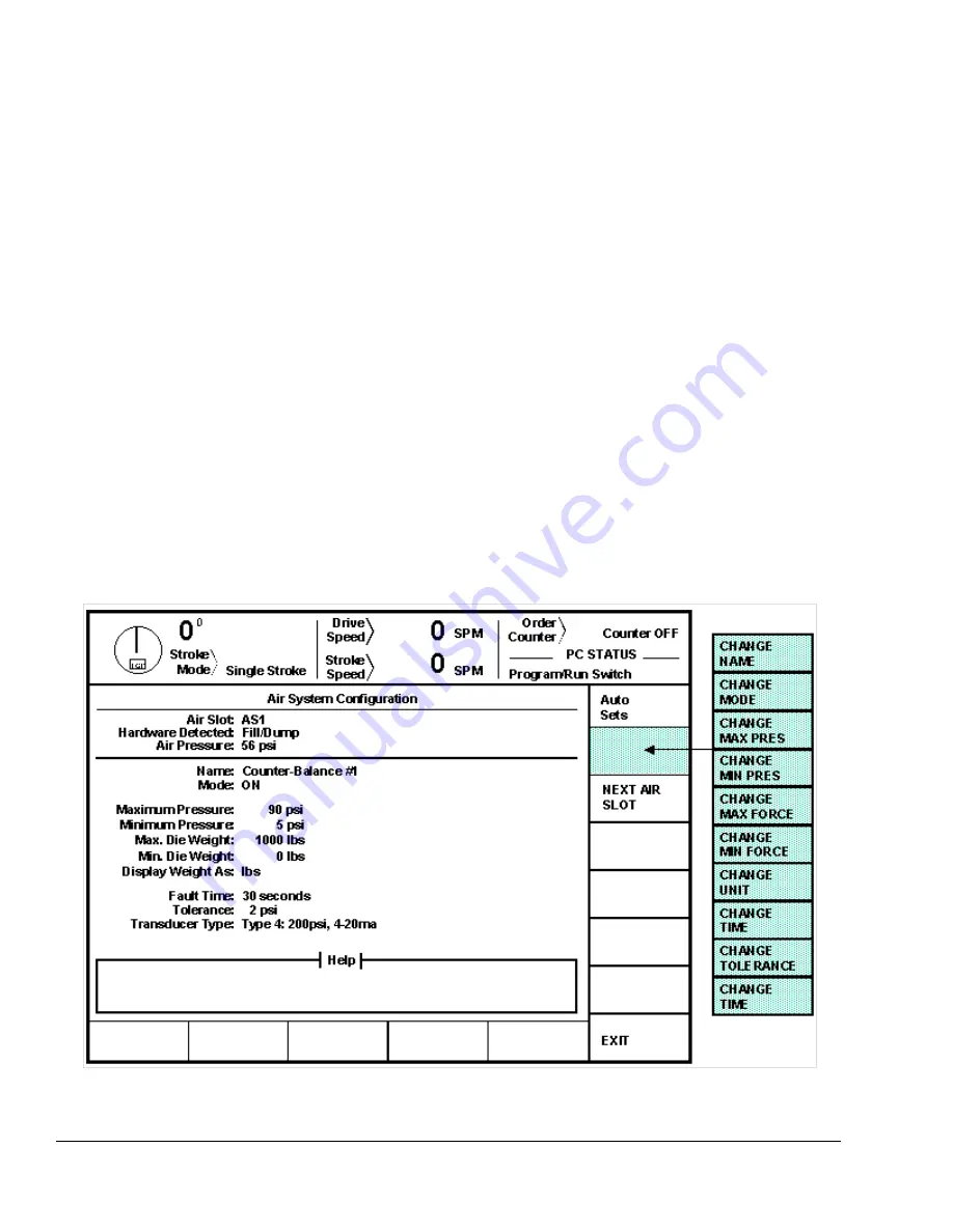
Figure 4.2:
Example Air Configuration Screen
Section 4.2 Configuring the Auto-Setup board
The ASM must be configured for the each shut height and pressure module that is installed on it. The
configuration necessary depends on the particular kind of module.
Section 4.2.1 Configuring Counterbalance, Cushion, and Hydraulic Overload Modules
Counterbalances and cushions are conceptually very similar and use essentially the same control
techniques. Hydraulic overloads are somewhat different but are usually air controlled systems (there are
some non-air controlled hydraulic overloads but the auto-setup board does not support them at this
time). To get to the configuration screen for cushion, counterbalance, and hydraulic overload modules:
a) Go to the “Auto Sets” screen. This screen is reached by pressing the “AUTO SETS” softkey in
the Main Menu or Press Control screen.
b) With the RUN/PROG key switch in the PROG position, press the “CONFIGURE” softkey and
enter the configuration code. Note that the code is provided separately from this manual for
administrative control.
c) Press the “CONFIGURE AIR” softkey.
At this point the screen should look similar to Figure 4.2.
Summary of Contents for OmniLink 5000
Page 5: ...April 17 2000 Manual Versio n 1 0 iv...
Page 38: ...April 17 2000 Manual Versio n 1 0 4 14...
Page 63: ...April 17 2000 Manual Versio n 1 0 B 2 Figure B 2 Typical Cushion Wiring Diagram...
Page 64: ...April 17 2000 Manual Versio n 1 0 B 3 Figure B 3 Conceptual Dual Resolver Mounting...
Page 65: ...April 17 2000 Manual Versio n 1 0 B 4 Figure B 4 Typical AMCI Dual Resolver Wiring Diagram...
Page 66: ...April 17 2000 Manual Versio n 1 0 B 5 Figure B 5 Typical GEMCO Dual Resolver Wiring Diagram...
Page 67: ...April 17 2000 Manual Versio n 1 0 B 6 Figure B 6 Conceptual Linear Transducer Mounting...
Page 68: ...April 17 2000 Manual Versio n 1 0 B 7 Figure B 7 Typical GEMCO Linear Transducer Wiring...
Page 71: ...April 17 2000 Manual Versio n 1 0 B 10...

