April 17, 2000
Man ual Versio n 1.0
5.1
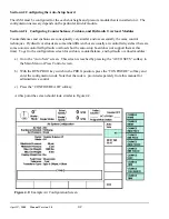
Figure 5.1:
Example Auto-Sets Screen
Section 5
Operation
The purpose of the Auto-Setup module is to allow automatic adjustment of such press systems as air
counterbalances, air cushions, air operated hydraulic overloads, and slide adjust systems to greatly
reduce setup time for different jobs, and to help ensure that these systems are adjusted correctly for
different jobs.
All operation of auto-setup functions, other than automatic adjustments to previously stored values
when the OmniLink 5000 recalls a job, start from the Auto-Sets screen. This screen is displayed when
the “AUTO SETS” softkey on the Main Menu or Press Control screen is pressed. The Auto-Sets screen
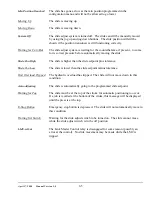
shows all configured functions and allows their settings to be adjusted. Figure 5.1 shows an example
Auto-Sets screen. Note that each configured function (slide adjust, counterbalance, cushion, or
hydraulic overload) has its own box with name, settings, position or pressure, status, and fault.
The main features of this screen are:
a) The module status gives the overall status of the auto setup module as a whole instead of the
status of a single sub-system, such as a counterbalance. When the module is functioning
properly, thus should read “All Conditions OK”. See section 6.1 for other diagnostic messages.
b) Each configured sub-system has a status. Under normal conditions, this status will read “At
Pressure” for air-based sub-systems such as counterbalances that are within the tolerance setting
of the set pressure. Slide sub-systems will read “In Position” when within the tolerance setting
Summary of Contents for OmniLink 5000
Page 5: ...April 17 2000 Manual Versio n 1 0 iv...
Page 38: ...April 17 2000 Manual Versio n 1 0 4 14...
Page 63: ...April 17 2000 Manual Versio n 1 0 B 2 Figure B 2 Typical Cushion Wiring Diagram...
Page 64: ...April 17 2000 Manual Versio n 1 0 B 3 Figure B 3 Conceptual Dual Resolver Mounting...
Page 65: ...April 17 2000 Manual Versio n 1 0 B 4 Figure B 4 Typical AMCI Dual Resolver Wiring Diagram...
Page 66: ...April 17 2000 Manual Versio n 1 0 B 5 Figure B 5 Typical GEMCO Dual Resolver Wiring Diagram...
Page 67: ...April 17 2000 Manual Versio n 1 0 B 6 Figure B 6 Conceptual Linear Transducer Mounting...
Page 68: ...April 17 2000 Manual Versio n 1 0 B 7 Figure B 7 Typical GEMCO Linear Transducer Wiring...
Page 71: ...April 17 2000 Manual Versio n 1 0 B 10...


