April 17, 2000
Man ual Versio n 1.0
C.1
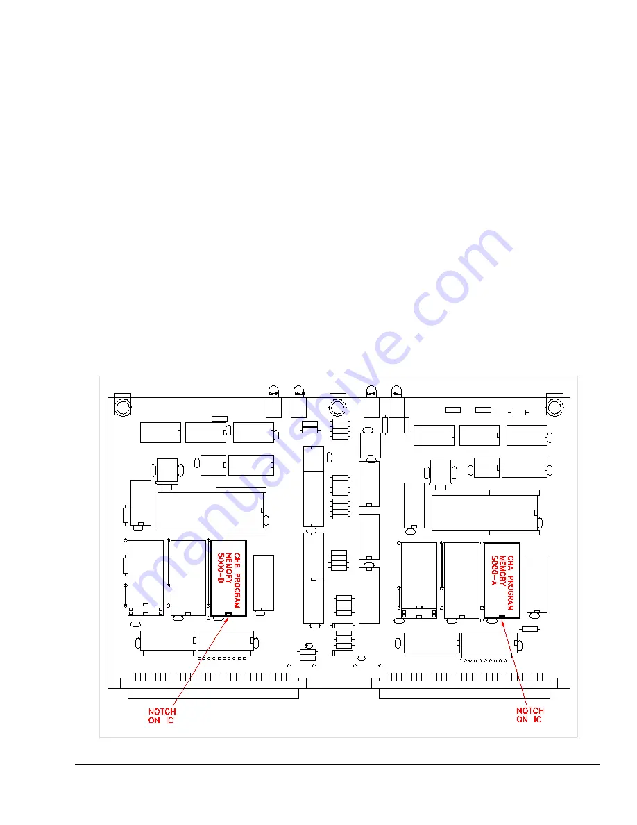
Figure C.1:
Logic Module Firmware Chip Locations
Appendix C Installation Of OmniLink 5000 Firmware
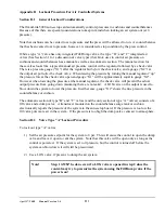
Firmware for the OmniLink 5000 press control is contained on two integrated circuits. Please follow
the instructions listed below for replacing the OmniLink 5000 firmware.
1) Remove all power from the OmniLink 5000 press control. Insure that the power to the OmniLink
card rack and the OmniLink Operator Interface terminal has been removed.
2) Remove the logic board from the card rack.
3) Note the location of the notches on integrated circuits 5000-A and 5000-B. Remove integrated
circuits 5000-A and 5000-B. See Figure C.1.
4) Insert the new 5000-A and 5000-B integrated circuits. Verify that the notches on the integrated
circuits are as shown in Figure C.1.
5) Insert the logic board in the card rack.
6) Apply power to the control and verify operation.
Summary of Contents for OmniLink 5000
Page 5: ...April 17 2000 Manual Versio n 1 0 iv...
Page 38: ...April 17 2000 Manual Versio n 1 0 4 14...
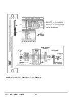
Page 63: ...April 17 2000 Manual Versio n 1 0 B 2 Figure B 2 Typical Cushion Wiring Diagram...
Page 64: ...April 17 2000 Manual Versio n 1 0 B 3 Figure B 3 Conceptual Dual Resolver Mounting...
Page 65: ...April 17 2000 Manual Versio n 1 0 B 4 Figure B 4 Typical AMCI Dual Resolver Wiring Diagram...
Page 66: ...April 17 2000 Manual Versio n 1 0 B 5 Figure B 5 Typical GEMCO Dual Resolver Wiring Diagram...
Page 67: ...April 17 2000 Manual Versio n 1 0 B 6 Figure B 6 Conceptual Linear Transducer Mounting...
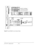
Page 68: ...April 17 2000 Manual Versio n 1 0 B 7 Figure B 7 Typical GEMCO Linear Transducer Wiring...
Page 71: ...April 17 2000 Manual Versio n 1 0 B 10...


