April 17, 2000
Man ual Versio n 1.0
D.2
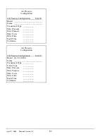
Note!
Step 1
MUST
be done even if a LOX valve is opened in step 2 since the
control may try to pressurize the system using the Fill/Dump valve if the
power is on!
Note!
Step 1
MUST
be done even if a LOX valve is opened in step 2 since the
control may try to pressurize the system using the Fill/Dump valve if the
power is on!
Section D.3
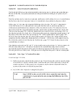
Valve Type “B” Lockout Procedure
The type “B” valve has a manual regulator in parallel with the automatic section that prevents the
pressure it is controlling from going below a minimum. To lock this valve out:
1) Set the pressure setpoint for the air system to 0 psi. At this point the manual regulator will try to
fill the system while the automatic section tries to dump.
2) Use the LOX valve (integrated into this type of valve) to dump the system and lock out the
manual section.
Section D.4
Valve Type “C” Lockout Procedure
When power is removed from the control or if the air system is turned OFF in the configuration menu, a
type “C” valve will revert to the manual section and the pressure will be no lower than the regulator
but
may be higher
because of the check valve.
To lock out a type “C” valve:
1) The air setpoint for the system to be locked out should be set to 0 psi OR the system must be
turned OFF in the configuration menu.
2) Use the LOX valve (integrated into this type of valve) to dump the system
even if the pressure
setpoint is set to 0 psi at the control.
This is necessary because if the control is powered down
intentionally or unintentionally the valve will revert to the manual regulator setting and may
attempt to fill the air system again.
If the LOX valve is opened when the system is still turned on and the pressure setpoint is not 0 psi, the
system will think it has a leak and will attempt to fill so it is important to turn the system OFF in the
configuration menu or set the pressure setpoint to 0 psi
before
the LOX valve is opened.
Summary of Contents for OmniLink 5000
Page 5: ...April 17 2000 Manual Versio n 1 0 iv...
Page 38: ...April 17 2000 Manual Versio n 1 0 4 14...
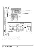
Page 63: ...April 17 2000 Manual Versio n 1 0 B 2 Figure B 2 Typical Cushion Wiring Diagram...
Page 64: ...April 17 2000 Manual Versio n 1 0 B 3 Figure B 3 Conceptual Dual Resolver Mounting...
Page 65: ...April 17 2000 Manual Versio n 1 0 B 4 Figure B 4 Typical AMCI Dual Resolver Wiring Diagram...
Page 66: ...April 17 2000 Manual Versio n 1 0 B 5 Figure B 5 Typical GEMCO Dual Resolver Wiring Diagram...
Page 67: ...April 17 2000 Manual Versio n 1 0 B 6 Figure B 6 Conceptual Linear Transducer Mounting...
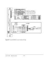
Page 68: ...April 17 2000 Manual Versio n 1 0 B 7 Figure B 7 Typical GEMCO Linear Transducer Wiring...
Page 71: ...April 17 2000 Manual Versio n 1 0 B 10...

