April 27, 2004 Manual Version 1.01
1.1
Section 1
Introduction
The Tonnage and Analog Signal Monitor Module is available as optional module with the OmniLink II
Press Automation Control. One of its primary purposes is to measure and display the force being
applied to the frame of a mechanical power press. The force applied during the working portion of the
stroke is compared with allowable limits based on the capacity of the machine and correct operation of
the die and material being used. Tonnages beyond these limits cause various types of stop signals to be
sent to the press control depending upon the importance of the overload. Present tonnage readings,
status messages, present tonnage limits, and detailed tonnage versus angle graphs (signatures) can be
examined or programmed through the same Operator Terminal as all other OmniLink II settings.
Section 1.1
Features
d
The OmniLink II Tonnage and Analog Signal Monitor Module provides four strain link connections
for use on two or four channel machines.
d
A crankshaft angle with a resolution of .021 degrees is supplied to the module by an internal
communication with the OmniLink II control. Position dependent parameters such as the working
portion of the stroke or data window settings are entered directly into the Tonnage and Analog Signal
Monitor Module requiring no external cam switches.
d
The same internal communication allows the module to instruct the OmniLink II control to Top
Stop, Cycle Stop, or Cycle Stop and turn Off the hydraulic overload outputs depending on the
present stroking mode and the type of tonnage alarm that has occurred.
d
Within the working portion of the stroke tonnage, limits for each job can be set for the maximum
allowable forward tonnage (High Limit), minimum required forward tonnage (Low Limit), and
maximum allowable reverse tonnage (Reverse Limit).
d
Inside the monitoring region additional data windows can be set to become active at specific
crankshaft angles, creating additional Low and High limits that become active only for the region
specified. Up to four data windows can be programmed for each job.
d
A maximum allowable forward tonnage limit is established when the module is installed, based on
the capacity of the machine (Machine Rating) and cannot be turned Off.
d
If desired, additional limits can be placed on the total tonnage that reflect the maximum allowable
tonnage at specific positions in the stroke.
d
Limits can be programmed manually, automatically calculated by the Tonnage and Analog Signal
Monitor Module, or recalled along with all other OmniLink II settings through the use of job setups.
d
Status messages for each channel indicate the first alarm condition that occurred during the stroke.
d
Each channel can be configured with a 15 character description indicating its physical location on the
press.
d
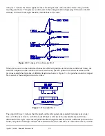
A graph of tonnage versus crankshaft angle can be displayed for each channel or the total. This
graph also shows the active areas of the data windows, when used.
Summary of Contents for OmniLink II
Page 5: ...April 27 2004 Manual Version 1 01 iv ...
Page 7: ...April 27 2004 Manual Version 1 01 1 2 ...
Page 21: ...April 27 2004 Manual Version 1 01 3 8 ...
Page 44: ...April 27 2004 Manual Version 1 01 4 23 Section 4 5 4 N A ...
Page 45: ...April 27 2004 Manual Version 1 01 4 24 ...
Page 69: ...April 27 2004 Manual Version 1 01 7 14 ...
Page 77: ...April 27 2004 Manual Version 1 01 8 8 ...


