background image

Notices

Chapter2. Notices

In order to ensure the reliable use of the equipment and personnel safety,

please observe the following items when installing, using and maintaining:

2.1 • Do not use this product in the following places: dust, fumes, conductive

dust,corrosive gas and combustible gas places; exposure to high temperature,
dew,rain occasion; vibration or shock situation; electric shock, fire and

misoperation will result in product damage and deterioration;
2.2 • In the end of the installation work, the need to ensure that there is no

foreign body on the ventilation surface, including dust and other packaging

items,otherwise it may result in poor heat dissipation during operation,
causing fire and error;

2.3 • To avoid of wiring and plug a electric cable plug, which would easily
lead to electric shock or cause damage to the circuit;

2.4 • Installation and wiring must be solid and reliable, poor contact may lead

to misoperation;
2.5 • For applications in interference is serious, input or output high

frequency signal cable should be shielded cable, in order to improve the
anti-jamming performance of the system; the external power supply must be

completely cut off, to carry out the installation and wiring operation,

otherwise it may cause electric shock or damage to equipment;
2.6 • This product is grounded through the grounding wire of the power supply

line. In order to avoid the electric shock, the grounding wire must be
connected with the earth;

2.7 • Please do not touch the terminal when the power is on,which may cause

electric shock and misoperation;
2.8 • Please tighten and cleaning the terminals when the power is off,These

operations may cause an electric shock when energized;
2.9 • After the power supply is closed, the connection or removal of the

communication signal cable, the cable connection of the expansion module or the

control unit, or the removal of the device can result in equipment damage and
misoperation;

2.10 • Do not disassemble the equipment to avoid damage to the internal
electrical components;

2.11 • Be sure to read this manual to fully confirm the safety, then the

program change, commissioning, start and stop operation. If you can not solve
the problem, please contact us.

Summary of Contents for LM-MX44U

Page 1: ...Professional Matrix 4x4 Switching System LM MX44U Instruction Manual Before using this product please read the instructions first and keep it properly ...

Page 2: ... button 8 Chapter6 Installation Instruction 9 6 1 Signal connection 9 6 2 RS232 communication interface connection 9 6 3 RJ45 for TCP IP control 9 6 4 RJ45 for RS232 control 10 6 5 Power connection 10 Chapter7 Communication Control Protocol 11 7 1 TCP IP control 11 7 2 RS232 control 11 7 3 Communication control protocol 11 Chapter8 Operating Instructions 13 Chapter9 Control Software 14 Chapter10 C...

Page 3: ...ed with a fragile label please preserve it carefully which will serve as the warranty certificate Please read this guide first when you have any problems The text has a detailed description of the device operation If you still have questions please contact us and we will give you a satisfactory answer as soon as possible If this manual has a version changes we will not inform you specially thank y...

Page 4: ...h frequency signal cable should be shielded cable in order to improve the anti jamming performance of the system the external power supply must be completely cut off to carry out the installation and wiring operation otherwise it may cause electric shock or damage to equipment 2 6 This product is grounded through the grounding wire of the power supply line In order to avoid the electric shock the ...

Page 5: ...curity and digital content protection capabilities 3 5 Support fast switching operation support infrared remote control The input and output board support card function can be hot swappable 3 6 Supports basic matrix control instructions and basic matrix functions With power down memory function with power off site protection function 3 7 Flexible control mode with the crystal button panel operatio...

Page 6: ...x Signal intensity T M D S 0 4Vpp Impedance 50Ω Input EDID EDID can read and write The maximum input distance 1920x1080 60hz less then 30 meters good cable The maximum output distance 1920x1080 60hz less then 20 meters good cable Serial port version RS232 Panel key Remote LAN port version TCP IP RS232 Panel key Remote Baudrate and protocol Baudrate 9600 data bits 8bits stop 1 no parity RJ45 serial...

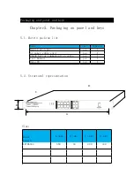
Page 7: ...eys 5 1 Matrix packing list Name Unit Numbers Matrix switcher pcs 1 AC power cable cord pcs 1 RS232 Serial communication cable pcs 1 User manual pcs 1 Data CD pcs 1 5 2 Structural representation Size Model Length A mm B mm C mm D mm LM MX44U 480 44 240 440 A B C D ...

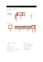
Page 8: ...nel and keys 5 3 Panel description Front Panel Back Panel Operation light power light IR Front panel buttons Power switch AC100 220V Input Signal input Signal input RJ45 as serial TCP IP port RS 232 output RS 232 input ...

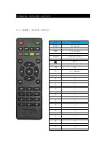
Page 9: ...Packaging and panel and keys 5 4 Remote control button Name Function SWITCH AV switch MENU System menu SOURCE System setting Exit OK ok All channel 0 0 1 1 2 2 3 3 4 4 5 5 6 6 7 7 8 8 9 9 ...

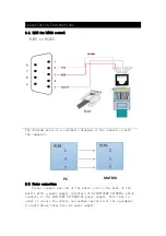
Page 10: ...ol The RS 232 port of the matrix is a D shaped 9 pin male connector the same as the serial port of the computer Pin descriptions are as follows Serial number Pin illustration 1 NC None 2 RXD Transmit Exchange Data RXD 3 TXD Receive Exchange Data TXD 4 NC None 5 GND Ground 6 NC None 7 NC None 8 NC None 9 NC None Attention matrix RS 232 port and the computer or the central control should pay attenti...

Page 11: ...e computer 6 5 Power connection Please connect one end of the power cord to the back of the matrix with a power supply interface of AC100 240V 50 60HZ which connects to the 100 240V 50 60HZ AC power supply Note that in order to ensure the safety and normal operation of the equipment a single phase three wire AC power supply PC MATRIX ...

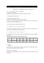
Page 12: ... is set to 9600 8 bit data bits 1 bit stop bits no parity bits and communication mode asynchronoushalf duplex serial communication 7 3 Communication control protocol The following protocols support all types of matrices including VGA series DVI series and HDMI series Matrix Remarks LM MX44Umatrix ID is 0 all protocols need add 0D For example 1D1V1 2 3 When ID is 0 you can use all the matrix ID val...

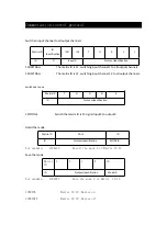
Page 13: ...E ID Protocolidentification 12TOONE Switchthe matrix ID is 12 signal input X to output X Recall the mode Matrix ID CALL ID ID Protocolidentification MODEID For example 12CALL2 Recall the mode 2 of Matrix ID 12 Save the mode Matrix ID S A V E ID ID Protocolidentification ModeID For example 12SAVE2 Save the mode 2 of Matrix ID 12 12BUZON Matrix ID 12 Buzzer on 12BUZOFF Matrix ID 12 Buzzer off Matrix...

Page 14: ... to output 3 channels press AV input 1 output 3 OK to switch the input 1 channel to all output channels press AV input 1 ALL OK EDID function key In standby mode Connect the EDID display screen or device to the output 1 channel power the matrix machine and display screen press the EDID key press the input port number to be written to EDID information press OK and then see the P light flashing for ...

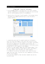
Page 15: ...ction at the serial port selection click the connection can connect successfully can start the communication the network version chooses the corresponding IP address to click the connection the network version setting refer to the IP address of the computer 2 Select the input channel number and output channel number click switch to complete the matrix quickly Switch control Switching to all input ...

Page 16: ... used oscilloscope or multimeter for testing if there is no signal output it is possible that the output line is broken or loose joints try to replace the wire 3 check whether the output port number is consistent with the controlled port number 4 does not belong to the above three kinds of situations may host internal fault please send professional maintenance If the POWER lamp does not light and ...

Reviews: