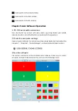
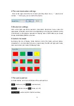
background image

8

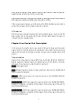
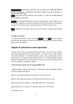
If you need an external audio, devices connect with external audio through the
headphone jack at both ends 3.5mm of audio cable

Input Signal Connection: Connect the computer or other signal source output devices
with input port of splittervia HDMI cable, VGA cable or DP line ;

If VGA require audio feature, use both ends with 3.5MM headphone jack cable to
connect the computer and the input Audio ports of device ;

3. Power on

After finishing connecting the cables that we have talked above , insert the 12V DC
power supply, turn on the power switch, power indicator lights isgreen for power-on
, the light is red for standby mode;

Chapter Four Device Port Description

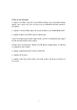
In the process of using the device, you need to first get to know each input and
output video port so that operate the equipment more skilled. Device input and
output ports consists of three parts, namely, an input section, output section, USB
section.

1.Input section

Input portion of the chassis rear panel INPUT box ,by A0: VGA, D0: DP, D1: HDMI, D2:
Mobile Signal, D3: Mobile Signal, D4: Mobile Signal, D5: DP, RS232 / IR, Audio
composed of nine input port, under function for each port:

A0:VGA

: VGA signal input;

D0:DP

:DP signal input,the maximum input resolution / refresh rate to 1920X1080 @

60HZ, backward compatible;

D1:HDMI

: HDMI input signal, the input resolution up to 1920 X1080 @ 60HZ,

backward compatible;

D2:Mobile Signal

: HDMI input signal, the input resolution up to 1920X1080 @ 60HZ,

backward compatible; compatible Mobile Signal mobile phone signal through the
Micro USB to HDMI input;

D3:Mobile Signal

: HDMI input signal, the input resolution up to 1920X1080 @ 60HZ,

backward compatible; compatible Mobile Signal mobile phone signal through the
Micro USB to HDMI input;

Summary of Contents for LM-TS71

Page 1: ...HD Quad Video Multi viewer LM TS71 User Manual...

Page 2: ...ting Instructions Table of Contents 1 Installation Notes 2 2 Product Introduction 4 3 Machine installation 7 4 Device Port Description 7 5 Remote Control Description 8 6 Key Instructions 12 7 Software...

Page 3: ...using the same protected You can not use unprotected power the power cord ground pin can not be destroyed 2 Power When you need tomove equipmentor other work must outage to shut off all power includi...

Page 4: ...rsonnel shall not open the case to avoid danger 2 Non dripping or splashing prohibited place any container with liquid items on the device 3 For the prevention of fire Prohibited a device near the fir...

Page 5: ...h performance its main function is to make the four HD or analog signals displayed simultaneously on a super high definition display unit under quad mode and contain PIP POP function This type of HD Q...

Page 6: ...Support display 4 way full HD signal simultaneously Input and output signal widely support audio and 3 5mm headphone jack support the left and right channel stereo output Single screen simultaneously...

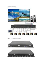
Page 7: ...6 3 System topology 4 Machines pictures and size...

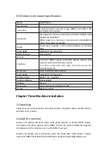
Page 8: ...l stereo for connecting stereo Resolution 1920 X 1080 60HZ optional Color depth 24bit 1677 ten thousand Control mode RS232 IR case key Control software Not available Voltage DC 12V Dimension 280mm L X...

Page 9: ...deo port so that operate the equipment more skilled Device input and output ports consists of three parts namely an input section output section USB section 1 Input section Input portion of the chassi...

Page 10: ...d high power audio playback Chapter Five Remote control operation Properly connect the output signal and display terminal then you need to properly connect theinput signal source and the device via re...

Page 11: ...hat achieve optimal effect when switching the resolution we must note the following Each time you press the SWITCH of remote control need about 2 seconds before you can switch to the next resolution I...

Page 12: ...ou can choose the signal as shown below 5 Settings of the window displays signal Signal 1 Signal 2 Signal 3 Signal 4 shows a fixed position but four signal ports can choose a different input source as...

Page 13: ...ch to signal 1 channel UA4Key sound switch to signal 1 channel 7 Brightness and contrast adjustment 7 1 While adjusting all signals window Press the MENU key to pop up menu then the region is set to F...

Page 14: ...Through the chassis button you can easily call in quick mode call mode are correspond with the remote controller the following only describes the purpose of each button Menu Up down left and right na...

Page 15: ...g RS 232 port to RJ45 network the other end of the RS 232 is connected with the equipment 2 Check the computer settings View computer COM port if is normal to see these steps Right click the desktop M...

Page 16: ...monitor Such as the physical resolution of display unit is 1920 1080 so you should choose 1920X1080 60HZ in this item 6 Switch the mode By clicking the icon of display mode shortcut control the mode...

Page 17: ...x33 define _RS232_LEFT_MSG left navigation 0x22 0x10 0x11 0x21 0x33 define _RS232_RIGHT_MSG right navigation 0x22 0x10 0x12 0x22 0x33 define _RS232_EXIT_MSG back exit 0x22 0x10 0x13 0x23 0x33 define _...

Page 18: ...x4C 0x33 define _RS232_N_MODE UA2 0x22 0x10 0x3D 0x4D 0x33 define _RS232_M_MODE UA3 0x22 0x10 0x3E 0x4e 0x33 define _RS232_K_MODE UA4 0x22 0x10 0x3F 0x4F 0x33 define _RS232_OUTPUT_1920 1080 60HZ 0x22...

Reviews: