background image

INSTALLATION INSTRUCTIONS 

TX

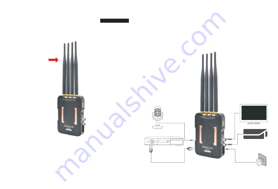
1. Install four 5dBi antennas on the transmitter

2. Connect transmitter to 12V Power-supply and turn on the power button, 
    OLED screen lighted up, the Signal and Frequency icons display, 
    Finished Starting-up )


Note: When transmitter SDI output, the SDI output can only be used 


          if SDI under loop output. 

4. Audio input, transmitter connected to the microphone, 


    (MODE key press 3S can switch the  internal and external sound).

12V power supply

Camera 

SDI loop output

SDI cable  connect

SDI monitor

HDMI

HDMI Cable

POO3

HD Player

HDMI

Connect the microphone

install antennas

4. For Transmitter inputs, either HDMI or SDI works, when the input is 
    SDI source, the SDI loop output(for local monitoring) is enabled."VIDEO" 
    icon will and only will display in OLED when a video input is properly 
    connected. 

Summary of Contents for LM-VT800

Page 1: ...Wireless HD Video Transmission Kit Version 1 0 2020 03 29 6TFS BOVBM PEFM 75 ...

Page 2: ...his manual Packing list Brief introduction Features 3 Mechanic information TX RX Interface information TX RX Installation instructions TX RX Product specifications OLED Screen Description 17 Trouble Shooting 19 Notices Description Contents ...

Page 3: ... please feel free to contact us or the dealer The company reserves the authority to amend the specification PACKING LIST TX 1 RX 1 SDI cable 1 RS232 cable 1 Antenna 4 Power Supply 12V 2A 1 Double nut 1 BRIEF INTRODUCTION FEATURES Wireless full HD video transmission Min 50ms low latency enables no waiting for wonderful image receiving Reliable overvoltage protection for better ensuring the safety o...

Page 4: ...Y F Type Battery Plate 5 8G Antenna Interface Audio IN OLED Screen CH Button Mode switch button OK Button LAN interface SDI LOOP OUT Power Switch 5 8G Antenna Interface Audio out OLED Screen CH Button Mode switch button OK Button LAN interface Power Switch SONY F Type Battery Plate MECHANIC INFORMATION TX ...

Page 5: ... input if not input at the same time which one is first input which one is preferred 11 DC IN input power supply 12V 2A 12 LAN External network port INTERFACE INFORMATION TX 1 MODE Button SW2 6S long press 3S long press No item Parameter Remark 6S long press WPS pairing Frequency witching No item Parameter Remark 4 OLED Screen No item Parameter Remark External audio input and video source audio op...

Page 6: ...ng press No item Parameter Remark 6S long press WPS pairing Frequency witching 6 Audio out No item Parameter Remark NC NC P12V Default set with out reserved for 12V voltage output 1 2 NC TXD 3 4 GND RXD 5 6 GND No item Parameter Remark NC Data transmit TX Data receive RX No item Parameter Remark No item Parameter Remark 10 DC IN input power supply 12V 2A 11 LAN External network port 1 3 2 4 5 6 3 ...

Page 7: ...DI under loop output 4 Audio input transmitter connected to the microphone MODE key press 3S can switch the internal and external sound 12V power supply Camera SDI loop output SDI cable connect SDI monitor HDMI HDMI Cable POO3 HD Player H D M I Connect the microphone install antennas 4 For Transmitter inputs either HDMI or SDI works when the input is SDI source the SDI loop output for local monito...

Page 8: ...en lighted up the Signal and Frequency icons display Finished Starting up 3 For Receiver outputs all HDMI SDI interface can output synchronously The Signal icon shows as a X in OLED when network between Transmitter and Receiver disconnected or connecting the Signal icon display properly when network connected VIDEO icon will and only will display on OLED when the video works properly 4 Audio outpu...

Page 9: ...ompression Format External Audio Support line in audio input IO port signal return Support Tally signal return Interface Standard HDMI input 1 SDI port 2 1 input 1 Loop Through 232 interface 1 DC 5 5 power supply input 1 CH button 1 MODE OLED 1 OK button 1 LINE IN 1 RJ45 interface 1 Tally socket 1 Operating Power Supply DC12V 2A with Part 6677 Power Supply Range Power Consumption RX Operating Freq...

Page 10: ...ing Mode 5 Indicates current working frequency Frequency RX Model Status Blank Icon Indication Contents Model Status Signal icon X Signal bar VIDEO Connecting Blank Network connection success No Video input Video source connected successfully VIDEO RTSP Video RTSP Streaming Point to Point Transmitting Mode 5 Indicates current working frequency Frequency Blank Signal icon Blank No Video input VIDEO...

Page 11: ...e code of TX and RX There is other transmitter which is under working condition near the receiver No Video Signal received Transmitter and video source are not connected The video source is turned OFF Video source were NOT switched to SDI HDMI output Bad contact of cable of transmitter Abnormal working of transmitter Problem with cable between TX and video source Player NOT support the output reso...

Page 12: ...deo output black screen after changing video source resolution If still failed to obtain video after this operation please power off and reset the transmission kits 5 Please power off and reset the kits if failed to connect for minutes after frequency channel switched 6 Please replug the HDMI and check TV Monitor is working or standby when transmission kits connected normally but failed to output ...

Reviews: