Doc Title
Linkplay WiFiAudio-A76 Specification
Number
WMB20170117
Version
1.2
Document No.: WMB20170117
Page 17 of 21
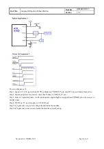
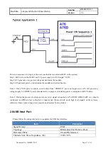
Power on sequence #2: (Apply to the user case that there is external MCU in the system)
Step 1: MCU turn on the DC/DC and 5V power supply to A76 through “5VIN”
Step 2:A76 generate every power voltage needed inside the module.
Step3:A76 generate power-on reset inside the module and system boot up.
Note 1: Once 5VIN power is stable, current drain from “VDDRTC” pin is no longer exist, A76 will generate a
voltage supply to VDDRTC power domain itself, on purpose of reducing power consumption of RTC battery.
Note 2: During the process of system power-on, every signal connected to A76(I2S,I2C,GPIO,UART etc..) should
configured as GPIO and set to High-Z or input mode. Please strictly avoid high level signals on these traces,
otherwise it may cause wrong power sequence and system boot up failed.
2.6 USB Host Port
Please follow the design rule below to populate the USB host interface:
Item
Parameter
Signal Group
USB
Topology
Differential Pair Point-to-Point
Reference Plane
Ground Referenced
Characteristic Trace Impedance (Zo)
90 Ω ±10%


