background image


Page 9 of 12 

4


Maintenance 


4.1


Towing Pin Assembling 


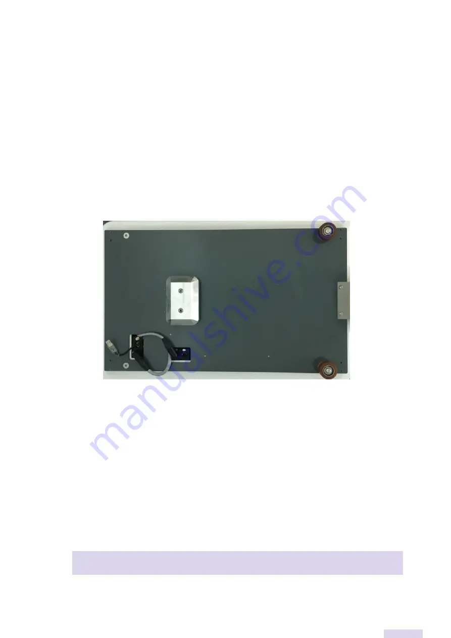
To assemble the Towing Pin on the MiR, you should check if the top cover is already cut so you 
can  place  the  system  on  top  of  the  MiR.  You  should  be  aware  of  the  power  supply  and 
emergency stop while conditioning the cables. After installing the system, you must connect the 
plugs according to the connection diagram. Finally, place the 4 screws and tighten them. 


4.2


Towing Pin Disassembling 


Disassembling  the  MiR  Towing  Pin  is  a  relatively  easy  process.  To  perform  some  of  the 
maintenance procedures, the Towing Pin must be disassembled from the MiR. To do so, you 
must loosen the 4 fastening screws and pull the entire structure out. You will have access to the 
entire Towing Pin system inside the MiR. 


4.3


Preventive maintenance 


Before performing any work on the Towing Pin, check if the MiR is turned off. 


Component 

Maintenance 

Period 

Summary of Contents for MIR100

Page 1: ...Towing Pin DESIGNED FOR MIR100 200 User Manual Version 2 1 Date 28 10 2019...

Page 2: ...Page 2 of 12...

Page 3: ...sion 5 2 2 Basic Specifications 6 3 Functioning Modes 6 3 1 Manual mode 6 3 2 Automatic mode 7 3 3 Safety 8 3 4 Troubleshooting 8 4 Maintenance 9 4 1 Towing Pin Mounting 9 4 2 Towing Pin Dismantling 9...

Page 4: ...n this manual the user can interpret the Towing Pin s operating schematics in automatic mode when the MiR is running a mission or in manual mode when there is a need to raise or lower the pin without...

Page 5: ...Page 5 of 12 2 General 2 1System General Vision In the images below you can check the dimensions in mm of the MiR with Towing Pin and the specifications of the car to transport...

Page 6: ...in s functioning modes according to the MiR s operating status 3 1Manual mode This functioning mode allows the operator to raise and lower the pin of the Towing Pin To do so the operator will have to...

Page 7: ...tomatic mode In automatic mode pin up and down management is done by the MiR during the execution of the current mission The user must ensure that the mission starts with the pin down The commands tha...

Page 8: ...t should be avoided Both registers 13 and 14 cannot be set to 1 Both registers 7 and 8 cannot be set to 1 Records 7 and 8 should only be at 1 if the pin is either down or fully up according to the fun...

Page 9: ...g to the connection diagram Finally place the 4 screws and tighten them 4 2Towing Pin Disassembling Disassembling the MiR Towing Pin is a relatively easy process To perform some of the maintenance pro...

Page 10: ...le Spindle lubrication 6 months Transmission Belt Check belt tension and wear 6 months Index Check index wear 6 months 4 4Wear parts list and Spare parts Component Qty Product Ref Index 1 Unit 5002 Tr...

Page 11: ...Page 11 of 12...

Page 12: ...ra 351 256 028 909 info link devices eu Go global with Link Our knowledge and experience will help you to enhance your productivity levels and increase your profit Start right now scaling your busines...

Reviews: