background image

Connecting the Auto-Sensing Hubs to Other Hubs,
Switches, or Routers

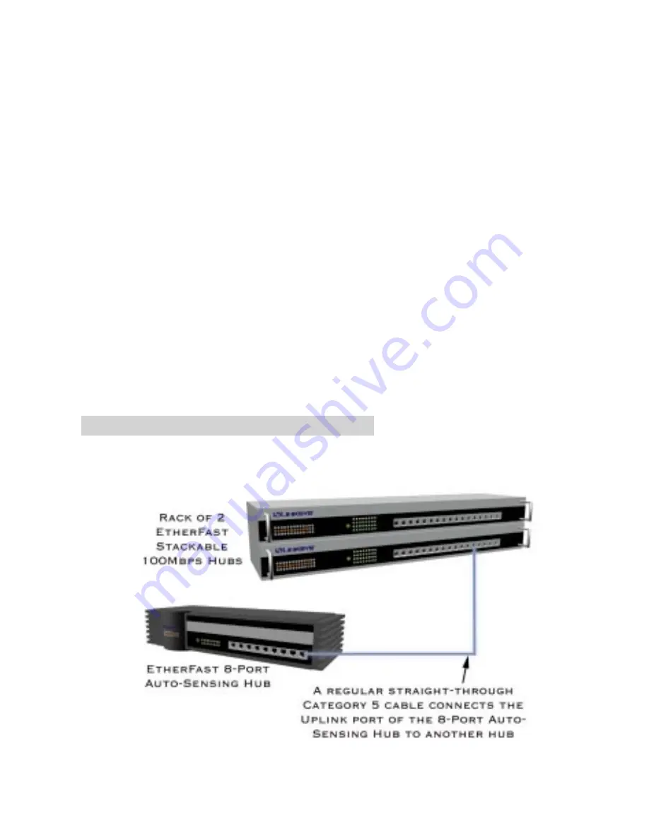
Like most hubs, the Auto-Sensing Hubs can be uplinked to 10Mbps or
100Mbps hubs, stackable hubs, switches, or routers. The front of each hub
has an Uplink port for this purpose.

If you are connecting the hub to a Fast Ethernet hub, router, or switch,
remember that Fast Ethernet rules only allow two hubs to be connected
together, or cascaded, within a single repeater domain.

To uplink the hub, simply connect a regular straight-through Category 5
cable from the Auto-Sensing Hub’s Uplink port to any regular network  
port on the hub, switch, or router being uplinked. The Auto-Sensing Hub
will automatically determine the optimum speed of the device being
attached to it.

Remember that while the Uplink port is in use, the port adjacent to it must
remain open, and should not be connected to any cable or node. See page 4
for important limitations when cascading hubs.

Uplinking the Hub

8

Summary of Contents for EFAH05W

Page 1: ...this guide to install these Linksys products EtherFast 10 100 5 Port Hub EFAH05W EtherFast 10 100 8 Port Hub EFAH08W EtherFast 10 100 16 Port Hub EFAH16W User Guide EtherFast 10 100 16 Port Rack Mountable Hub EFAH16 EtherFast 10 100 24 Port Rack Mountable Hub EFAH24 ...

Page 2: ...mplied or statutory with respect to its products or the contents or use of this documentation and all accompanying software and specifically disclaims its quality performance merchantability or fitness for any particular purpose Linksys reserves the right to revise or update its products software or documentation without obligation to notify any individual or entity Please direct all inquiries to ...

Page 3: ...er Optic Expansion Modules 7 Mounting the Hub 7 Connecting Nodes to the Hub 7 Uplinking the Hub 8 Uplinking the 5 Port Hub 9 Powering On and Resetting the Hub 10 Appendix Twisted Pair Cabling 11 Installing Add On Modules 12 Fiber Optic Modules 13 100BaseTX Distance Extender Module 16 Specifications 18 Customer Support 19 ...
Page 4: ...you plug into 10Mbps or 100Mbps hubs stacking hubs switches or backbones for easy future expansion Advanced error handling auto partitioning data collision con trol and auto polarity correction protect your data during transmissions Compatible with virtually all operating systems like Windows 98 Windows 95 Windows NT and Novell NetWare the professional grade Auto Sensing series of hubs offers your...

Page 5: ...rs of Category 5 unshielded twisted pair UTP cabling 100BaseTX supports high speed signaling and is relatively inexpensive Because it uses four wires for data transmission and the same packet format packet length error control and management information as 10BaseT 100BaseTX can be made to communicate with slower 10BaseT equipment when routed through a switch This backward compatibility is one of 1...

Page 6: ...ceed 100 meters 328 feet in length Fast Ethernet networks require Category 5 cabling Category 5 cabling can be obtained at most computer stores or you can crimp your own See page 11 for cabling specifications Here are some important cabling rules to fol low Computers should never be connected directly together on a network They should always be connected to a hub Only two 100Mbps Fast Ethernet hub...

Page 7: ... Sensing hub your package also includes rack mounting hardware suitable for securing the hub in a stan dard hub rack Front and Back Panels The front of each Auto Sensing Hub includes 10 100 RJ 45 ports that can be connected to workstations computers or file servers with straight through category 5 cabling an Uplink port that can be used for connecting to other hubs switches or routers with straigh...

Page 8: ...s 100 ON if a given port is operating at 100Mbps OFF if the port is running at 10Mbps Link Act ON or flickering if a given port is sending or receiving data OFF if the port is not con nected to a node FX1 FX2 ON if the hub s optional expansion module is installed Flickering when receiving or transmit ting data FX2 is on when a dual port module is being used FX1 is on when a single port or dual por...

Page 9: ...ermined by the speed of the hardware or node connect ed to the port Connect each of your PCs workstations file servers print servers or other network nodes to the Auto Sensing Hub one by one Each node should be connected to the hub with a straight through RJ 45 Category 5 cable Each cable should be less than 100 meters 328 feet in length Ready to use network cables of various lengths can be purcha...

Page 10: ...e connected together or cascaded within a single repeater domain To uplink the hub simply connect a regular straight through Category 5 cable from the Auto Sensing Hub s Uplink port to any regular network port on the hub switch or router being uplinked The Auto Sensing Hub will automatically determine the optimum speed of the device being attached to it Remember that while the Uplink port is in us...

Page 11: ... port automatically becomes capable of sending data over an uplink cable of up to 100 meters 328 feet The LED marked SW will light up indicating that a 100 meter uplink can be established Please note that in order for the distance extending switch to become active all four remaining ports on your 5 Port hub must be running at 100Mbps remember that one port on the hub is lost when the hub is uplink...

Page 12: ... AC electrical power cord into the back of the hub Turn on the hub The hub will put itself through a series of diagnostic tests which shouldn t take more than just a few seconds then begin scanning the ports for live nodes The installation is complete Resetting the Hub To reset the hub turn the unit off for at least three seconds and then turn it back on If you have a rack mountable model you can ...

Page 13: ...also wires 1 2 3 and 6 at the other end In a crossed cable the order of the wires change from one end to the other wire 1 becomes 3 and 2 becomes 6 and vice versa The color code for the 4 wires should be as follows Wire 1 white with an orange stripe Wire 2 orange Wire 3 white with a green stripe Wire 6 green The other four wires have to be connected as follows Wire 4 blue Wire 5 white with a blue ...

Page 14: ... the chips and the components on the add on module are facing up If the module has a daughter board a bigger board mounted on the main board of the add on module the bottom of the daughter board should be facing up Insert the module into the back of the hub 6 The add on module will slide in until it comes to a stop Push the mod ule to make sure it makes a proper connection Note Do not use too much...

Page 15: ...onnector on the other If you are looking at the back of the hub the connector on the right is the receiver and the connector on the left is the transmitter The connectors are also labeled on the top of the fiber port These labels can not be seen after the module is installed so make sure that you look before you slide it in Each Distance Extender Modules has a switch on the back for Full Duplex or...

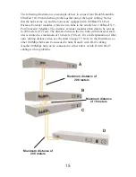
Page 16: ...nnector module an SC to ST converter has to be obtained or the ST connector may be replaced by an SC Connector Note Changing connectors has to be done professionally and proper tools have to be used If you have never worked with fiber cabling seek the help of a professional who is familiar with the medium The following table shows the distance limitation when connecting the Linksys Fiber modules D...

Page 17: ...nder modules allow data to be sent up to 208 meters 672 feet The distance between the two hubs with tranceiver mod ules is limited to a maximum of 16 meters 50 feet For a full explanation of fiber optic cabling distance rules see the chart on page 15 Note In the illustration no other 100Mbps hubs can be cascaded to hubs B and C with RJ 45 cabling Another 100Mbps hub can be connected to either hub ...

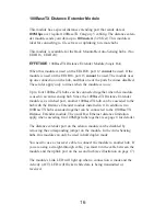
Page 18: ... module is used in an auto sensing hub Since the 100BaseTX Distance Extender module is a switched port another 100BaseTX hub can be cascaded to the hub with the Distance Extender module installed in it In addition two 100BaseTX hubs cascaded together can be connected to the 100BaseTX Distance Extender module The usual Fast Ethernet distance limitation apply when cascading two 100Mbps hubs together...

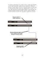
Page 19: ...e the maximum distance between two uplinked hubs is 5 meters 16 4 feet With the distance extender module installed on one of the hubs the maximum distance becomes 100 meters 328 feet Only one distance extender module is needed for the long distance uplink to be activated Regular Uplink 5 meters Maximum Distance Extender Uplink 100 meters Maximum Regular Straight Through Cable Regular Uplink 5 mete...

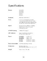
Page 20: ... Each port runs at 10Mbps or 100Mbps independent of other ports speeds dual speed per port UTP STP Cabling 100BaseTX Category 5 LED Indicators Power 10 100 Col 100 Link Act SW on 5 Port Uplink only Power EFAH05W 7 5VDC 1A EFAH08W 5VDC 3 6 A EFAH16W 5VDC 3 6 A EFAH16 90 250VAC 50 60Hz EFAH24 90 250VAC 50 60Hz Power Consumption 8 22 Watts depending on model Dimensions Desktop models vary Rack mounta...

Page 21: ...10 100 Auto Sensing Hub contact Linksys Customer Support at one of the phone num bers or Internet addresses below Customer Support 949 261 1288 Fax 949 261 8868 Bulletin Board 949 261 2888 33 6K 8 N 1 E mail support linksys com Web http www linksys com FTP Site ftp linksys com 19 ...

Page 22: ... Copyright 1999 Linksys All Rights Reserved Printed in the USA http www linksys com ...

Reviews: