Installation Guide Linear Motors
ENG
Page 28 / 47
P01-48-HP EX protected
NTI AG / LinMot
4.2 Mounting the motor
Please attend to the safety instructions in the chapter 2 during the assembling!
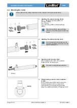
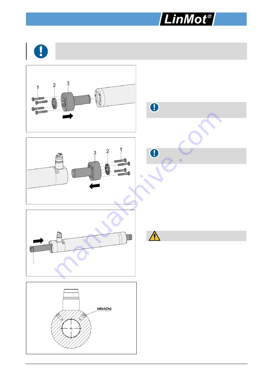
1. Installing the external bearing (front).
Pos .1: Hexagon head screw M6 x 35
(Torque = 6 Nm)
Pos. 2: Wiper
Pos. 3: Bearing (PB01) or Bearing flange
(PB03)
Mount the bearing / bearing flange
with care, since the plastic sleeve may
break.
2. Installing the external bearing (rear).
The corresponding bearings must be
ordered separately! A selection can be
found in section 3.4.
3. Insert the slider into the stator.
After installation, the notch of the slider is
located on the connector side.
The slider is magnetically attracted.
4. If fluid cooling is used, remove headless
screws.
For the stator variant with liquid cooling, the
headless screws must be removed and
replaced with the corresponding threaded
plugs. See additional details in Paragraph 4.8.5
Groove
Summary of Contents for 0150-4370
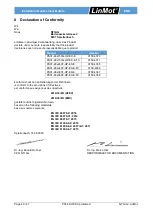
Page 42: ...Installation Guide Linear Motors ENG Page 42 47 P01 48 HP EX protected NTI AG LinMot ...
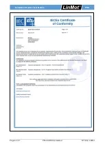
Page 43: ...Installation Guide Linear Motors ENG NTI AG LinMot P01 48 HP EX protected Page 43 47 ...
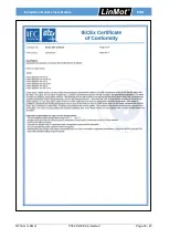
Page 44: ...Installation Guide Linear Motors ENG Page 44 47 P01 48 HP EX protected NTI AG LinMot ...
Page 46: ...Installation Guide Linear Motors ENG Page 46 47 P01 48 HP EX protected NTI AG LinMot ...


