Installation Guide Linear Rotary Motors
ENG
NTI AG / LinMot
PR02-70
Page 17 / 41
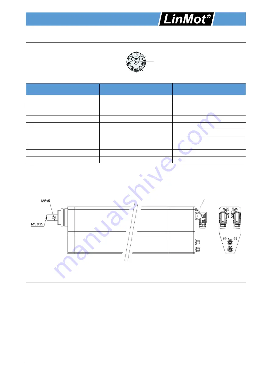
5.2 Connector Wiring Electric Pusher
View: Motor connector, plug side
Connector wiring
Electric Pusher
R-Connector
Wire colour
Motor cable
Ph 1+ / Ph A
1
red
Ph 1- / Ph B
2
pink
Ph 2+ / Ph C
3
blue
Ph 2- / (-)
4
grey
+5VDC
A
white
GND
B
Inner shield
Sin
C
yellow
Cos
D
green
Temp.
E
black
Shield
Housing
Outer shield
5.3 Connection of Air
Configuration of air connection
Pos. 1: Air connection with option (L01) / "Pull" with option Pn. Pusher
Pos. 2: "Push" with option Pn. Pusher
The PR02-70 is optionally equipped with a hollow shaft for air feed-through or for integration of a pneumatic
pusher. Depending on the option, there are several pneumatic push-in fittings (external hexagon M5) for a Ø
4 mm hose at the rear of the motor, above the electrical plug connections. Inside the motor, a Ø 4 mm air
hose is routed along the rotary shaft. This enables the user to realise pneumatic applications with an
operating pressure of max. 6 bar.
Depending on the order situation (option "hollow shaft" or option "pneumatic pusher"), 1 or 2 push-in
connections are pre-assembled. The user also has the option of mounting a pneumatic push-in fitting on the
front of the shaft. For this purpose, the user has an M5 (15 mm deep) in the axial direction and an M5 (5 mm
deep, recommended push-in fitting KAH04-M5 with a total length of 17 mm) in the radial direction. The
through hole in the rotary shaft is Ø 4 mm.
In the case of vacuum application, it is recommended to use a unit with sufficient power, as experience has
shown that all air coupling points generate small losses.
Push-in fitting
External hexagon M5
for a Ø 4 mm hose
2
4
1
A
B
C
D
E
3


