Installation Guide Linear Motors
ENG
NTI AG / LinMot
P10-70-SSC / P10-70-SSC-D02
Page 25 / 32
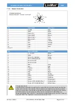
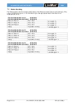
7.1.2 Sensor Connector
Shielded twisted pair
Encoder Kabel d = 0.5 mm
2
/ 0.25 mm
2
Pin
P10-70-SSC
Wire Color
1
+5VDC
Red
2
GND
Black
3
Sense +5V
White
4
Sense GND
Brown
5
Motor Link C +
Pink
6
Motor Link C -
Grey
7
Sin +
Yellow
8
Sin -
Orange
9
Cos +
Green
10
Cos -
Blue
11 to 17
n. c.
-
Pin
P10-70-SSC-D02
Wire Color
1
3…13 VDC
White
2
GND
Brown
3
Sense Vcc (optional)
Green
4
Sense GND (optional)
Yellow
5
Do not connect
-
6
Do not connect
-
7
Sine +
Grey
8
Sine -
Pink
9
Blue
10
Cosine -
Red
11
Ref +
Black
12
Ref -
Purple
13
Hall U
Grey-Red
14
Hall V
Red-Blue
15
Hall W
White-Green
16
Temp + (PTC 400/20k Char.)*
Yellow-Brown
17
Temp - (PTC 400/20k Char.)*
White-Yellow
* Temperatur circuit
The temperature evaluation circiut must be powered from the encoder supply and must be
at the same potential. The grounds of the temperature evaluation circuit and the encoder
have to be connected. The encoder must have been powered on for at least 50 ms, before
valid temperatures can be measured. If the encoder is powered off, 200k Ohms are
measured between Pins 16 and 17. The maximum voltage between Pin 16 and 17 must not
exceed 16 VDC. The maximum current must not exceed 15 mA.
10
4
14
15
17
13
16
1
7
9
11
5
3
2
12
6
8


