background image

  Installation guide 


NTI AG / LinMot

®

                           www.LinMot.com                                        21 / 37


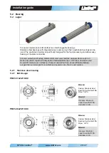
4.2  Connector 

4.2  Stecker 


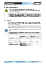
For a complete encapsulation the connector is welded to the housing of the stator.  
The connector is designed for tightening and made of stainless steel.  
The cable connectors are optionally available in protection class IP67 and IP69K. Motor 
connector and cable connector are firmly bolted together. Dimensions and tightening torque 
are shown in the following figure. 


Zum Zweck einer vollständigen Kapselung ist der Stecker auf das Gehäuse des Motors 
geschweisst. Der Stecker ist in Edelstahl und zum Festziehen ausgeführt.  
Die Kabelstecker werden optional in der Schutzart IP67 und IP69k angeboten. Motorstecker 
und Kabelstecker werden miteinander fest verschraubt. Dimensionen und Anziehdrehmoment, 
sind in der nachfolgenden Abbildung ersichtlich.  


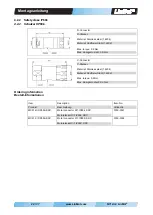
4.2.1  Safety class IP67 

4.2.1  Schutzart IP67 


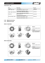
R-Connector 

R-Stecker 


Material: Vernickelt 

Material: Nickel-plated 


Max. torque: 0.6 Nm 

Max. Anzugsmoment: 0.6 Nm  


C-Connector 

C-Stecker 


Material: Vernickelt 

Material: Nickel-plated 


Max. torque: 0.6 Nm 

Max. Anzugsmoment: 0.6 Nm  


Ordering information  

Bestell-Informationen


Item 

Produkt 

Description 

Beschreibung 

Item-No. 

Artikel-Nr. 

MC01-R/f 

Motor connector R/f 

Motorstecker R/f 

0150-3129 

MC01-C/f 

Motor connector C/f 

Motorstecker C/f 

0150-3080 


Summary of Contents for PS01-37x120F-HP-SSC-R/ FC

Page 1: ...nMot Linear motors Motor type PS01 37x120F HP SSC R FC PS01 48x240F SSC C w FC PS01 48x360F SSC C w FC Montageanleitung LinMot Linearmotoren Motor Typ PS01 37x120F HP SSC R FC PS01 48x240F SSC C w FC PS01 48x360F SSC C w FC ...

Page 2: ...Version 1 2 Mi 20141229 Dok Nr 0185 0014 E D ...

Page 3: ...lation altitude 33 8 Stator dimensions 34 8 1 PS01 37x120F HP SSC R FC 34 8 2 PS01 48x240F SSC C w FC 35 8 3 PS01 48x360F SSC C w FC 35 9 Declaration of Conformity and CE marking 36 Inhalt 1 Allgemeines 2 1 1 Einleitung 2 1 2 Symbolerklärung 2 1 3 Haftung 3 1 4 Urheberschutz 3 2 Warnhinweise 4 3 Montagehinweise 7 3 1 Betriebsbedingungen 7 3 2 Montageanleitung Linear Motor 7 3 3 Demontage der Lager...

Page 4: ...bt den Zusammenbau die Montage die Wartung sowie den Transport und Lagerung von Linearmotoren Es sind zwei Sprachversionen englisch deutsch in dem Handbuch eingeschlossen Englisch ist durch eine reguläre Schrift gekennzeichnet Die deutsche Übersetzung ist anhand der grauen Umrahmung und der kursiven Schriftart erkennbar Das Dokument wendet sich an Elektriker Monteure Servicetechniker und Lagerpers...

Page 5: ...Drives Mit dem Kauf bestätigen Sie dass Sie die in der Montageanleitung aufgeführten Warnungen gelesen und verstanden haben Zu jeder Lieferung wird ein Hinweis Blatt mit demselben Inhalt geliefert Bitte fügen Sie dieses Hinweisblatt auch bei falls Sie LinMot Motoren als Komponenten oder in Maschinen weiterverkaufen Im Übrigen verweisen wir auf unsere Allgemeinen Geschäftsbedingungen in der jeweils...

Page 6: ...id getting too close to sliders Herzschrittmacher Implantierter Defibrillator Läufer können die Funktion von Herzschrittmachern und implantierten Defibrillatoren beeinflussen Für die Dauer einer zu starken Annäherung an ein Magnetfeld schalten diese Geräte in einen Testmodus und funktionieren nicht richtig Als Träger eines dieser Geräte halten Sie zwischen Herzschrittmacher bzw Defibrillator und L...

Page 7: ...net with improper tools the magnet may break The heat that arises may demagnetise the magnet The magnet will oxidise and disintegrate due to the damaged coating Machining the sliders and the magnets they contain is not permitted Mechanische Bearbeitung Neodym Magnete sind spröde hitzeempfindlich und oxidieren leicht Wenn zwei Magnete kollidieren können sie zersplittern Scharfkantige Splitter könne...

Page 8: ...Beschädigung des Stators führen Effects on people According to the current level of knowledge magnetic fields of permanent magnets do not have a measurable positive or negative effect on people It is unlikely that permanent magnets constitute a health risk but it cannot be ruled out entirely For your own safety avoid constant contact with magnets Store large magnets at least one meter away from yo...

Page 9: ...en 90 C HP Motoren 120 C 3 2 Instructions for installing the linear motor 3 2 Montageanleitung Linear Motor Please attend to the safety instructions in chapter 2 during the assembling Beachten Sie unbedingt die Sicherheitshinweise im Kapitel 2 während der Montage Option a Stainless bearing 1 Mounting bearing front Pos 1 Cylinder screw M5 3 5 Nm for PS01 37 Cylinder screw M6 6 Nm for PS01 48 Pos 2 ...

Page 10: ... 5 Nm for PS01 37 Cylinder screw M6 6 Nm for PS01 48 Pos 2 Wiper Pos 3 Ring for the bearing Pos 4 Tube for the bearing Option a Edelstahl Lager 2 Einbau des externen Lagers hinten Pos 1 Zylinderschraube M5 3 5 Nm bei PS01 37 Zylinderschraube M6 6 Nm bei PS01 48 Pos 2 Abstreiferdichtung Pos 3 Ring für Lager Pos 4 Hülse für Lager Option b Washdown WD bearing 2 Mounting bearing behind Pos 1 Cylinder ...

Page 11: ...s in section 3 9 3 Mounting on page 19 4 Gewindestifte Bei Statoren in der Variante mit Flüssigkeitskühlung müssen die Gewindestifte entfernt und mit den entsprechenden Steckverschraubungen ersetzt werden Siehe weitere Details im Abschnitt 3 9 3 Montage auf S 19 3 3 Disassembly of the bearing tube 3 3 Demontage der Lagerhülse At first the wiper is removed from the stainless steel bearing with a pl...

Page 12: ...ld ist im Abschnitt 8 Stator Abmessungen auf S 34 ff abgebildet Make sure the torque on the clamp plate screws does not exceed the maximum value Max Anzugsmoment muss beachtet werden Thread Gewinde Max torque for screw Stainless steel A4 Max Anzugsmoment der Schraube INOX A4 M 5 3 5 Nm M 6 6 Nm 3 5 Mounting the payload to the slider 3 5 Montage der Last am Läufer The load is mounted as a fixed bea...

Page 13: ...r Last zugewandten Seite des Läufers angesetzt werden siehe Abbildung unten Slider Läufer Thread Gewinde Max torque for screw Stainless steel A4 Max Anzugsmoment der Schraube INOX A4 19 mm M 8 16 Nm 27 mm M 10 32 Nm Incorrect attachment Torsional stress on slider Falsche Montage Torsion auf dem Läufer Correct attachment Richtige Montage 3 6 Moving slider installation 3 6 Einbauart Bewegter Läufer ...

Page 14: ... and the stator is the moving part The load is attached to the stator which is mounted on a linear guide In order to avoid an overconstrained bearing mount and compensate for alignment errors the slider may be mounted on one end in a fixed bearing with a spherical axial bearing On the opposite end the slider is mounted in a floating bearing Mounting kits are available for mounting the slider see t...

Page 15: ...s High Flex Kabel für Schleppkettanwendungen eingesetzt werden 1 Mount stator to its support bearing 1 Montage des Stators auf dem Führungswagen 2 Insert slider into stator 2 Einschieben des Läufers in den Stator 3 Put a spacer wood plasic aluminium with thickness 15 mm between slider and linear guide The spacer prevents injuries to the hands and damage to the slider surface 3 Platzieren eines Abs...

Page 16: ...ce the floating bearing on the slider and attach to its support do not tighten the screws Note The slider is allowed to extend into the floating bearing no more than 15 mm 5 Montage des Loslagers Schrauben noch nicht festziehen Wichtig Der Läufer darf max 15 mm ins Loslager hineinragen 6 Move stator back end to the fixed end of slider center slider in stator and tighten the screw 6 Verschieben des...

Page 17: ... 60 mm PL01 27 60 mm 60 mm 3 8 2 Minimum distance from slider to metallic parts 3 8 2 Minimalabstände Läufer zu metallischen Teilen When installing linear motors in modules with metal parts near the slider undesired forces can arise due to magnetic attraction or eddy currents These generally manifest as erratic and jerky positioning or reduced dynamics of the linear motor In order to avoid this mi...

Page 18: ...gte Verlustwärme wird durch die Flüssigkeitskühlung abgeführt Wird der Motor mit einer Flüssigkeitskühlung betrieben steigt die kontinuierliche Nennleistung im Vergleich zur Selbstkühlung um ein Vielfaches 3 9 1 Design of water cooling 3 9 1 Auslegung der Wasserkühlung T_Flow Flow temperature T_Back Return temperature T T_Back T_Flow T_Water Mean coolant temperature T_Flow T_Back 2 Q_Water Flow p ...

Page 19: ...of cont power dissipation Pv_Max Bestimmung der max anfallenden Dauer Verlustleistung Pv_Max Example Motor P01 48x360F T_Water 25 C Pv_Max 324 W Beispiel Motor P01 48x360F T_Water 25 C Pv_Max 324 W The coolant temperature must not fall below the ambient temperature otherwise there is a risk of condensation When used and stored in a frost prone area corrosion protection e g Clariant has to be added...

Page 20: ...eine möglichst gleichmässige Kühlung des Motors zu erreichen sollte die max Differenz zwischen Vor und Rücklauftemperatur 10 C nicht überschreiten Determination of water pressure p Bestimmung des Wasserdrucks p Example Q_Water 0 7 l min p 1 8 bar Beispiel Q_Water 0 7 l min p 1 8 bar The required water pressure to inject the required water flow depends on the hydraulic resistance of the cooling cir...

Page 21: ...otection agents is to be avoided Corrosion protection products must be matched to the materials of the cooling circuit The cooling circuit consists of copper tubes Das Mischen von verschiedenen Korrosionsschutzmittel ist zu vermeiden Korrosionsschutzmittel müssen auf die Materialien des Kühlkreislaufs abgestimmt werden Bei den Kühlsystem handelt es sich um Rohre aus Kupfer 3 9 3 Mounting 3 9 3 Mon...

Page 22: ... to the stator is not a high flex cable For moving cable applications please use the special LinMot KS high flex suitable for cable tracks Für die INOX Linearmotoren sind 2 Kabelarten verfügbar Das Standard Motorkabel ist für die stationäre Verlegung bestimmt Das High Flex Kabel Schleppkettentauglich kommt bei bewegten Kabelanwendungen zum Einsatz Pay attention to the specific bending radius fixed...

Page 23: ...ecker ist in Edelstahl und zum Festziehen ausgeführt Die Kabelstecker werden optional in der Schutzart IP67 und IP69k angeboten Motorstecker und Kabelstecker werden miteinander fest verschraubt Dimensionen und Anziehdrehmoment sind in der nachfolgenden Abbildung ersichtlich 4 2 1 Safety class IP67 4 2 1 Schutzart IP67 R Connector R Stecker Material Vernickelt Material Nickel plated Max torque 0 6 ...

Page 24: ...smoment 0 6 Nm C Connector C Stecker Material Stainless steel 1 4404 Material Rostfreier Stahl 1 4404 Max torque 0 6 Nm Max Anzugsmoment 0 6 Nm Ordering information Bestell Informationen Item Produkt Description Beschreibung Item No Artikel Nr MC01 R f IP69K SSC Motor connector R f IP69k SSC Motorstecker R f IP69k SSC 0150 3347 MC01 C f IP69K SSC Motor connector C f IP69K SSC Motorstecker C f IP69...

Page 25: ...sions and material of fixed bearing kit Material Spherical washer conical seat Stainless steel Abmessungen und Material des Festlager Zubehörs Material Kugelscheibe Kegelpfanne Stahl rostfrei Part list Teile Liste PLF01 20 SS Item no 0150 3296 PLF01 28 SS Item no 0150 3297 2 Spherical washer 2 Kugelscheiben DIN 6319 C M8 DIN 6319 C M10 2 Conical seat 2 Kegelpfannen DIN 6319 D M8 DIN 6319 D M10 1 S...

Page 26: ...d material of floating bearing kit Material Housing Stainless steel 1 4305 Bearing Nitrile butadiene rubber Spring steel DIN17223 Abmessungen und Material des Loslagers Material Gehäuse Edelstahl 1 4305 Lager Nitril Butadien Gummi Mit Federstahl DIN17223 Ordering information Bestell Informationen Item Artikel Item No Artikel Nr Slider Läufer Thread Gewinde d1 d2 d3 D4 L PLL01 19 0150 3335 19mm M5 ...

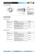
Page 27: ...dene austauschbare Lager an Neben den INOX Lagern mit integrierten Abstreiferdichtungen steht dem Anwender eine Kunststoff Variante zur Verfügung Diese ist speziell auf die Lebensmittelverarbeitung ausgerichtet und ermöglicht ein einfaches Ausspülen des Stators und Läufers 5 2 1 Stainless steel bearing 5 2 1 INOX Lager PB01 37x24 P SSC Material Casing Stainless steel Bearing Synthetical FDA Wiper ...

Page 28: ...aring to PBR01 37x24 SSC Hülse für Lager PBR01 37x24 SSC 0150 3292 PAW01 19 Wiper for PL01 19 Abstreiferdichtung für PL01 19 0150 3223 PB01 37x24 P SSC Bearing kit for PS01 37x120 SSC Lagersatz für PS01 37x120 SSC 0150 3290 PS01 48x240 SSC Item Produkt Description Beschreibung Item No Artikel Nr PBR01 48x25 SSC Ring for bearing to PS01 48x SSC Ring für Lager zu PS01 48x SSC 0150 3278 PBH01 48x25 P...

Page 29: ...ülse für Lager PBR01 48x25 80 SSC Hülse für Lager PBR01 48x25 80 SSC 0150 3402 PAW01 27 Wiper for PL01 27 Abstreiferdichtung für PL01 27 0150 3224 PB01 48x25 80 P SSC Bearing kit for PS01 48x360 SSC Lagersatz für PS01 48x360 SSC 0150 3413 5 2 2 Washdown bearing 5 2 2 Washdown Lager PB01 37x24 P WD Material Bearing Synthetical FDA Material Lager Kunststoff FDA PB01 48x25 P WD Material Bearing Synth...

Page 30: ...01 48x240 SSC Lager für PS01 48x240 SSC 0150 3271 5 3 Auxiliary tools for the disassembly of the bearing tube 5 3 Hilfstools für die Demontage der Lagerhülse PBR01 37 SSC AT PBR01 48 SSC AT Ordering information Bestell Informationen Item Produkt Description Beschreibung Item No Artikel Nr PBR01 37 SSC AT Auxiliary tools for PBR01 37 SSC Hilfstools für PBR01 37 SSC 0150 2606 PBR01 48 SSC AT Auxilia...

Page 31: ...Steckers verbunden Do not connect or disconnect motor when there is power on the servo drive Use only double shielded original LinMot cable Cables from other sources must be checked precisely before commissioning Incorrect connections can destroy the drive and stator Motorstecker nur ein oder ausstecken wenn keine Spannung am Servo Drive anliegt Für die Motorverkabelung darf nur das doppelt geschi...

Page 32: ...5 Sensor Sine GND Yellow Brown Pin G Pin F 33 k Sensor Cosine GND Green Brown Pin H Pin F 33 k Temp Sensor GND Black Brown Pin L Pin F 10k Phase GND Pin A B C D Pin F 20 M All Pin Shield Pin A L Housing 20 M PS01 48x240F SSC C 0150 1267 PS01 48x240F SSC C FC 0150 1268 Phase1 Phase1 Red Orange Pin A Pin B 1 1 Phase2 Phase2 Blue Gray Pin C Pin D 1 1 5V GND White Brown Pin E Pin F 155 Sensor Sine GND...

Page 33: ...n p 9 Überprüfen und ggf Auswechseln des INOX Lagers nur Hülse Abstreifer oder Kunststofflagers Siehe Abschnitt 3 3 Demontage der Lagerhülse auf S 9 Slider Läufer Check whether the slider surface is clean and not scratched Scratched sliders must be replaced otherwise clean the slider See Section 6 3 2 Cleaning on p 32 Kontrolle ob Läuferoberfläche sauber und nicht verkratzt ist Verkratzte Läufer m...

Page 34: ...onstruktionen mit nicht magnetischem Material z B Holz abzudecken Läufer und Stator mit einem weichen Wegwerfpapier idealerweise unter Zuhilfenahme von LU06 Reinigungsspray alternativ Brennsprit oder Alkohol reinigen Übliche Reinigungsmittel in der Lebensmittelindustrie dürfen ebenfalls genutzt werden Abschliessend Läufer gemäss Abschnitt 3 2 Montageanleitung Linear Motor einführen 6 3 3 Cleaning ...

Page 35: ...her conditions The air in the storage area must not contain any harmful gases The max installation altitude is 4 000 m above sea level From 1 000 m derating of 1 C per 100 m is to be considered for air cooling LinMot Läufer dürfen ausschliesslich in der Orginalverpackung transportiert und gelagert werden Die Läufer sollten erst beim Einbau aus der Verpackung genommen werden Der Lagerraum muss troc...

Page 36: ...Montageanleitung 34 37 www LinMot com NTI AG LinMot 8 Stator dimensions 8 Stator Abmessungen 8 1 PS01 37x120F HP SSC R FC 8 1 PS01 37x120F HP SSC R FC in mm ...

Page 37: ...Installation guide NTI AG LinMot www LinMot com 35 37 8 2 PS01 48x240F SSC C w FC 8 2 PS01 48x240F SSC C w FC in mm 8 3 PS01 48x360F SSC C w FC 8 3 PS01 48x360F SSC C w FC in mm ...

Page 38: ...0 1268 PS01 48x240F SSC C FC 0150 1274 PS01 48x240F SSC C Cw 0150 1275 PS01 48x240F SSC C CW FC 0150 1270 PS01 48x360F SSC C 0150 1271 PS01 48x360F SSC C FC 0150 2365 PS01 48x360F SSC C Cw 0150 2366 PS01 48x360F SSC C CW FC konform ist mit den Anforderungen der Richtlinien is conform to the provisions of directives est conformé aux exigences des directives 2006 95 EC LVD 2004 10B EC EMCD gestützt ...

Page 39: ...Installation guide NTI AG LinMot www LinMot com 37 37 Note Notizen ...

Page 40: ... com Tech Support 41 0 56 544 71 00 support linmot com Tech Support Skype skype support linmot Fax 41 0 56 419 91 92 Web http www linmot com USA LinMot Inc 204 E Morrissey Dr Elkhorn WI 53121 Sales Administration 877 546 3270 262 743 2555 Tech Support 877 804 0718 262 743 1284 Fax 800 463 8708 262 723 6688 E Mail usasales linmot com Web http www linmotusa com ...

Reviews: