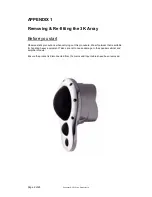
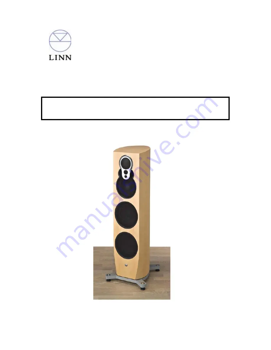
background image

Page 1 of 29 

Copyright © 2010 Linn Products Ltd. 


Standard Fault Finding – Artikulat 350 & Klimax 350 Loudspeakers 


THIS PROCEDURE TO BE CARRIED OUT BY AUTHORISED LINN RETAILERS AND 

SERVICE AGENTS ONLY 

Summary of Contents for Klimax 350

Page 1: ...Page 1 of 29 Copyright 2010 Linn Products Ltd Standard Fault Finding Artikulat 350 Klimax 350 Loudspeakers THIS PROCEDURE TO BE CARRIED OUT BY AUTHORISED LINN RETAILERS AND SERVICE AGENTS ONLY...

Page 2: ...see APPENDIX 1 For Removing Re fitting Amplifier Module see APPENDIX 2 For Removing Re fitting the Upper Servo Bass Drive Unit see APPENDIX 3 For Removing Re fitting the Lower Servo Bass Drive unit s...

Page 3: ...RT Is there evidence that the Loudspeakers have been over driven i e listened to at excessively high volume levels Do the Loudspeaker s fail to power on Are the fault Symptoms on one or both Loudspeak...

Page 4: ...follow the Amplifier Module Do the symptoms follow the 3K Array Check all other units cables etc in the system Stage 2 1 3K Array Amplifier Module Upper or Lower bass drivers Swap 3K Array over from t...

Page 5: ...eakers check the location of mains leads and signal cables so that they are situated away from any device that may generate interference Check all other devices in the system for faults i e Source pro...

Page 6: ...ore you start Observe static precautions when carrying out this procedure Wear footwear that is suitable for handling heavy equipment Take care not to cause damage to the speaker cabinet and amplifier...

Page 7: ...Remove the 7 securing bolts around the 3K array 2 Taking care not to damage any of the speaker grilles carefully pull the 3K array to disconnect it from the rear connector 3 Place the 3K array in a s...

Page 8: ...ng the rear connector locates in position when fitted 2 Fit the top mounting bolt first to hold the 3K Array in position Gently move the 3K Array from side to side to ensure the gap between the 3K Arr...

Page 9: ...uitable for handling heavy equipment Take care not to cause damage to the speaker cabinet and amplifier module It is advisable that the following procedure is carried out by 2 people Ensure there is a...

Page 10: ...Remove the 2 bolts located at the bottom of the module 3 Carefully lean the amp module back until it is being supported by the strap Disconnect all the cables between the amp module and speaker 8 cabl...

Page 11: ...rom the securing bolt Other speakers have an insert within the cabinet 5 Ensure the module is being supported before moving the module towards the cabinet slightly and then removing the support strap...

Page 12: ...n the space between the fan and the back of the module 2 Carefully lift the module and guide the base of the module into position Be careful not to trap any of the cables underneath the module Once in...

Page 13: ...010 Linn Products Ltd 5 The support strap will now take the weight of the module You should check that the strap is straight 4 Refit the bolt and strap to the cabinet and if applicable the washer and...

Page 14: ...nce will be reduced 2 Reconnect the GREEN banded Red and Black speaker cable to the module where it is marked LOWER 8 BASS GREEN The speaker cables have either 2 or 4 cables terminated with a 4 way co...

Page 15: ...ule where it is marked UPPER 8 BASS YELLOW 5 Reconnect the YELLOW banded servo cable to the module where it is marked SERVO CABLE YELLOW at the top of the small cover plate 6 Connect the BLACK banded...

Page 16: ...s Ltd 7 Connect the WHITE banded Red and Blue speaker cable to the connector on the rear of the module marked MID PASSIVE O P 8 Connect the BLUE banded 3 K Array cable to the connector on the rear of...

Page 17: ...Red and Black speaker cable to the module where it is marked LOWER 8 BASS GREEN The speaker cables have either 2 or 4 cables terminated with a 4 way connector Ensure the speaker connectors are making...

Page 18: ...er cable to the module where it is marked UPPER 8 BASS YELLOW 5 Reconnect the YELLOW banded servo cable to the module where it is marked SERVO CABLE YELLOW at the top of the small cover plate 6 Reconn...

Page 19: ...he WHITE banded speaker cable to the module where it is marked MID WHITE 8 Reconnect the BLUE banded speaker cable to the module where it is marked SUPER TWEETER TWEETER BLUE Arrange the speaker cable...

Page 20: ...r plate on the amplifier module 2 Using a 5mm hex key fit the washer and bolt to each side of the lower module mounting holes Given that the brackets are suspended it is sometimes necessary to re alig...

Page 21: ...0 Linn Products Ltd 3 Fit the remaining 4 washers and bolts Don t tighten them fully until all 6 bolts are in place Once all 6 bolts are in tighten them all up 4 Refit the 2 bolts and washers located...

Page 22: ...ic precautions when carrying out this procedure Wear footwear that is suitable for handling heavy equipment Take care not to cause damage to the speaker cabinet and amplifier module It is advisable th...

Page 23: ...2010 Linn Products Ltd 2 Carefully remove the grill and trim ring 3 Remove all 6 screws and washers securing the drive unit 1 Remove the 3K Array as per the procedure in APPENDIX 1 REMOVING THE UPPER...

Page 24: ...from solder blobs or splashes while using the soldering iron 1 Solder the red and black wires onto the drive unit in the correct position Note It may be advisable to protect the cabinet from solder b...

Page 25: ...n ensuring the wires were positioned under the unit magnet before it is lowered into position Ensure the flat edges of the speaker unit are facing the top and bottom of the cabinet as shown Insert and...

Page 26: ...ic precautions when carrying out this procedure Wear footwear that is suitable for handling heavy equipment Take care not to cause damage to the speaker cabinet and amplifier module It is advisable th...

Page 27: ...Linn Products Ltd 2 Carefully remove the grill and trim ring 3 Remove all 6 screws and washers securing the drive unit 1 Decide which of the two Lower Bass Drive Units are to be removed REMOVING THE...

Page 28: ...anded grey accelerometer cable to the connector on the drive unit Solder the red and black wires to the drive unit in the correct position Note It may be advisable to protect the cabinet from solder b...

Page 29: ...Page 29 of 29 Copyright 2010 Linn Products Ltd 3 Carefully fit the grill and trim ring 4 Ensure the grill wire runs horizontally and vertically with the cabinet sides...

Reviews: